How to design holes for components – useful tips

Sharing a common understanding on how components are manufactured is indeed the key to improving the procurement process for designers.  This is why we are enriching our “meviy guide” for components design. This blog post focuses on the basic design considerations on hole machining. Let’s see what the different types of holes are and how to design holes for your custom mechanical parts avoiding some of the most common mistakes.

Basic information of Hole Machining

In the case of machining, holes are generally processed in the following steps:


  • Drilling a center hole.
  • Drilling a pilot hole (drilling process).
  • Performing specific machining operations based on the intended use. Examples are reaming, tapping, counterboring.
Understanding the different types of holes is the key to learning how to design holes. These are some of the different types of holes machining: Center hole drilling, pilot hole drilling, reaming, tapping and counterboring.
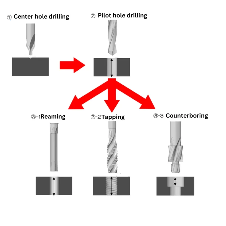
Let’s see below each hole’s information:

Center drilling

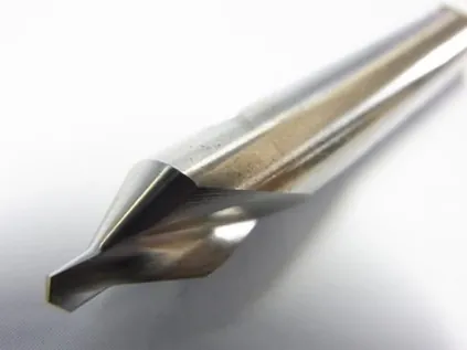
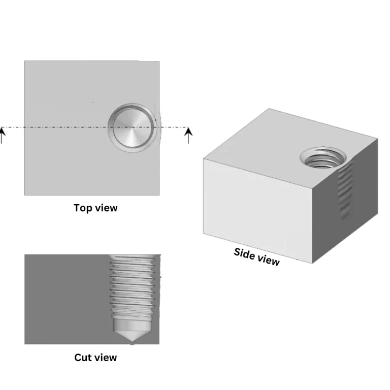
Center drilling involves creating a small indentation known as a center hole and it is made using a specialized tool called a center drill. The purpose of this indentation is to ensure precise positioning of the subsequent drilling operations.
Example of a center drill

Counterboring

Counterboring is the technique performed to ensure that the screw head does not protrude from the surface. While it is possible to perform counterboring using a regular end mill, for standardized screw counterboring, dedicated cutting tools for counterboring are often used.

Tapping

When creating holes for fastening parts with screws, tap machining is the best option. After the initial drilling process, tap machining is performed to create the threaded hole. A specialized cutting tool is used for this purpose, and in the case of CNC machining, a dedicated program called a tap cycle is used.

Example of a tapping

Reaming

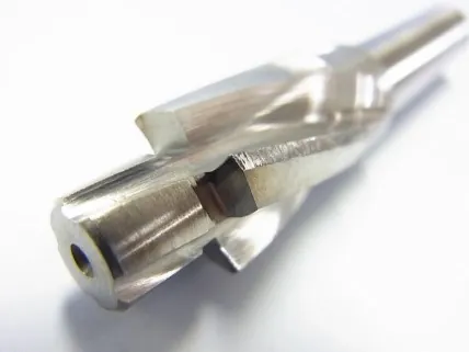
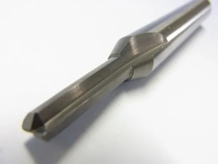
When precise fitting is required for pin insertion or mating with other components, it is necessary to create a clean, perfectly round hole on the inner surface. In such cases, reaming is performed after the initial drilling process. In the case of larger diameters, a specific tool can be used to achieve the desired quality.   Reaming is performed using a tool with cutting edges on its side. The reamer is rotated while slowly passing through the drilled hole, removing a small amount of material from the inner surface. It shaves the inner surface, resulting in a clean and highly accurate hole.   Reaming is used when a tolerance of approximately ±0.01mm relative to the hole diameter is required.
Example of a reamer

Drill machining

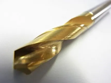
The basic process of machining this type of hole involves using a tool called a drill. It is mounted on the spindle of a machine and rotated while being moved up and down in a linear motion. The drilling action is performed by repeatedly plunging the drill bit into the workpiece. Since the drilling action involves multiple up and down motions, the resulting hole has an uneven and rough interior surface. This is commonly referred to as a “pilot hole.” If a simple hole is sufficient, then drilling alone is acceptable.
Example of a drill

How to design holes guide - common issues

Now, let’s discuss some common problems that arise from hole machining. There might indeed be misunderstandings and misalignments between the designer’s needs and the supplier’s capacity. Here, we will introduce common troubles related to holes, and we hope you find them helpful to learn better how to design holes for your custom parts.


Hole is too close to the edges - troubleshooting

A first significant factor that can cause issues with holes is the presence of holes near the edge.   During hole machining, the material is being pushed outward by the drill. If you try to create a hole very close to the edge, where the distance to the side is minimal, the surface may not be able to withstand the machining force. This will cause the side to bulge or deform.
Example of a design mistake where the hole is too close to the edge

Indeed, holes near the edge are structurally weak, and it is generally not recommended to design them that way.


To avoid such situations, it is advisable to maintain a minimum distance from the edge of at least the diameter of the hole. This is particularly important for threaded holes, as they are more prone to these issues, requiring extra attention.


If it is impossible to maintain the necessary distance in the design, an alternative approach is to perform additional machining on the side after the hole drilling process. This can help mitigate the “bulging” effect caused by the initial machining. However, introducing an additional machining step can increase costs and complexity.

Hole is too deep - troubleshooting

In hole machining, precision can be achieved for depths up to approximately 8 times the diameter. Beyond that depth, specialized processes are required to avoid any issues and errors in manufacturing.


With such deep holes, the tendency is for them to bend and the hole diameter to widen. Although high-precision deep-hole machining methods like honing are available, there are still limitations if the initial hole is bent. In such cases, another option is to use shape carving electrical discharge machining. Nonetheless, it’s important to remember that there are still limits to machining deep holes with high precision, depending on the shape. As a general rule, a depth of approximately 8 times the diameter is a good starting point.


For example, let’s imagine a part similar to the one shown in the figure below. It features small-diameter through-holes along the length of the block.

If you were to drill the hole from one direction only, it would bend. The drill gradually bends as it goes in, resulting in larger errors the further it moves away from the entrance.

Design mistake for a custom mechanical component where the hole is too deep.
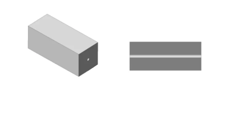
In cases where the hole is through-hole, one approach to minimize the effects of bending is to perform the drilling halfway from both sides. This type of machining is commonly known as “gun-drilling”.

Conclusions

As we’ve seen, there are various considerations on the manufacturing side depending on the purpose and shape of the hole. While there are still deeper aspects to holes, if you can firmly grasp the fundamental principles we discussed today, it is likely that you will be able to design in a way that can be easily accommodated by the manufacturing process.


Design has its own pain-points, and manufacturing also has its own requirements. It is important for both sides to understand each other’s perspectives and work together to achieve better product development.