BLOG » 3 Design Tips for Automatic Sheet Metal Quotations
3 Design Tips for Automatic Sheet Metal Quotations
Embarking on the journey of sheet metal procurement often becomes a complex maze, especially when coupled with the pursuit of operational efficiency. In the realm of sheet metal, design intricacies are paramount not only for making it difficult to get an automatic quote, but for affecting accuracy and to lead to potential production deformities. The pitfalls of manual processes, in fact, can unknowingly pave the way for design discrepancies that may affect the production stage, causing unintended deformations.
The idea that if a part can be designed then it can be produced is common among designers. However, it is important to remember that a 3D model is just a simulation of the final part. When modeling sheet metal parts on the CAD software, in fact, we must be cautious of the manufacturing requirements.
Our expert insights delve into these intricacies, illuminating the way to improve your designs to get your quote and avoid any production deformations. With our comprehensive understanding of automatic sheet metal quotations, we present you with more than just a solution – we provide you with a paradigm shift in the way you approach design, ensuring your projects sail smoothly from conception to creation.
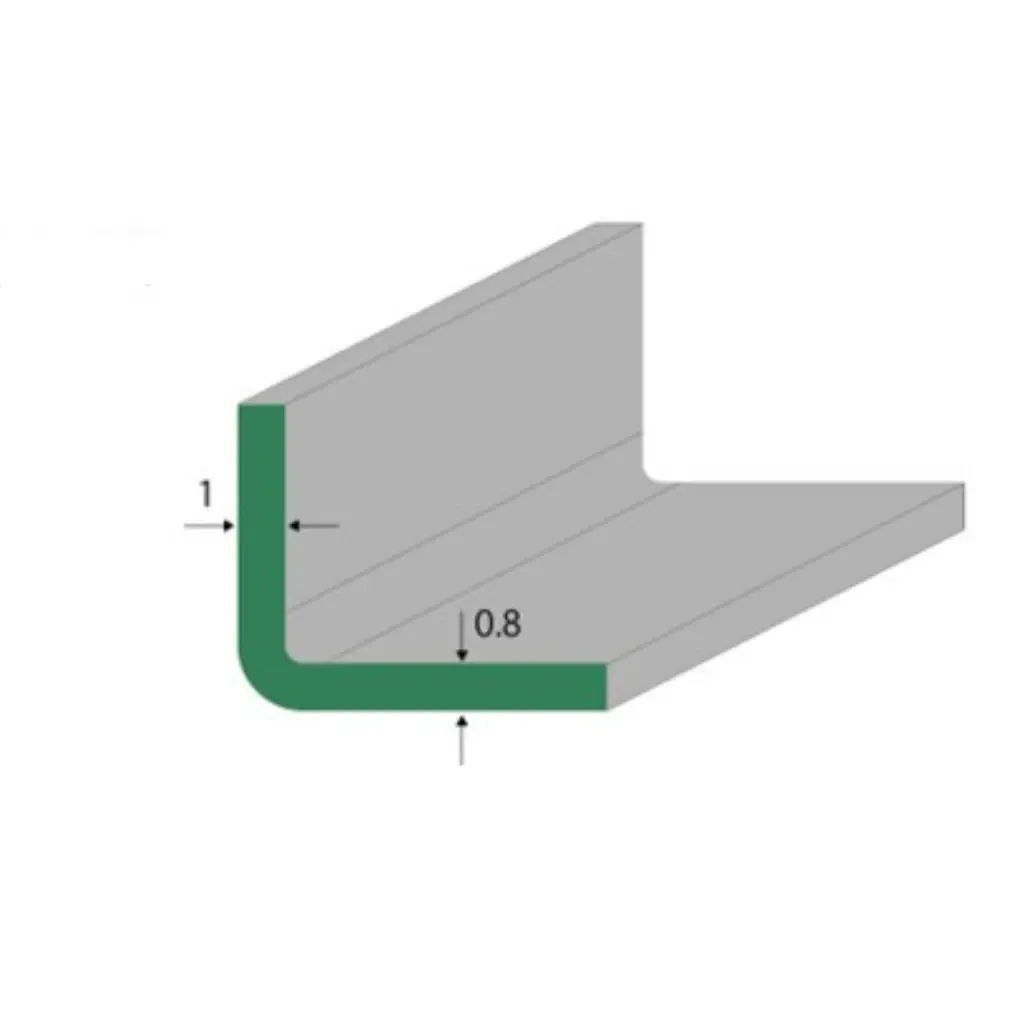
Sheet thickness and radius are two major factors that are intrinsically dependent on each other and that might affect the manufacturability of the component.
To maintain the final components’ structural integrity and to make it easier to be able to get an automatic quotation, it is essential to double check the thickness of each surface and to model the thickness of the parts uniformly.
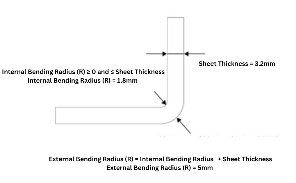
The second point to be considered to make sure to get an automatic quote regards the bending sections. In order to avoid any quotation issues, in fact, always ensure that the external bending radius (R) is equal to the sum of the internal radius (R) and the thickness of the sheet metal.
As it regards the internal radius, though, we highly recommend modelling it as greater or equal to 0 and less than or equal to the sheet thickness. The equation that reflects this pattern will then look like the below:
Internal Bending Radius (R) ≥ 0 and ≤ Sheet Thickness
Additionally, the minimum bending radius is determined by the punch used. The internal radius cannot be smaller than the punch’s shape, so it is not possible to bend with pin angles or excessively small radii. Use the internal radius (R) ≤ sheet thickness as a rough guideline.
Let’s see how this apply in the example below, which sees a sheet thickness of 3.2mm:
As mentioned, the Internal Bending Radius (R) has to be ≥ 0 and ≤ 3.2mm. We then designed it to be 1.8mm to make sure the final component will be manufactured according to our standards.
Consequently, the External Bending Radius (R) will equal 5mm (Internal Radius (R) + Sheet Thickness)
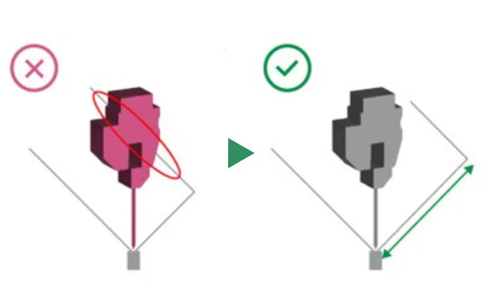
As a minimum guideline, the angle formed between the top of the rise wall and the U-bend should be 45° or less, meaning the length of the bottom surface should be longer than the rise height. To reliably avoid interference, it is recommended that the height of the bottom surface is at least twice the rise height.
Avoiding Interference with Mold in U-Bending
When bending sheet metal into a U-shape (U-bend), it’s important to pay attention to the dimensions of the bottom surface. If there isn’t sufficient length on the bottom surface in relation to the rise dimension, it may lead to interference with the mold.
As a minimum guideline, the angle formed between the top of the rise wall and the U-bend should be 45 degrees or less. In other words, the length of the bottom surface needs to be longer than the height of the rise. For a more reliable way to avoid interference, it’s recommended that the height of the bottom surface is at least twice the height of the rise.
Taking these precautions will help ensure that U-bending sheet metal doesn’t interfere with the mold.
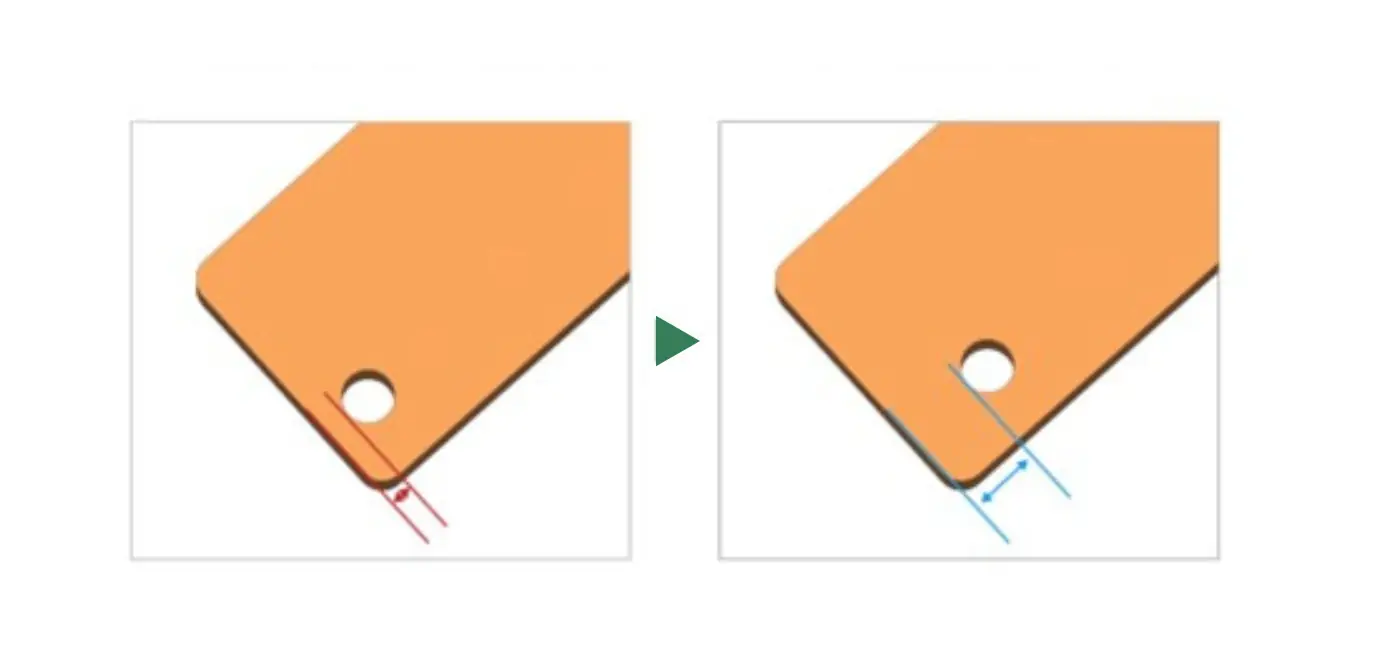
Specifying Minimum Distance Between Edge and Through-Hole
When creating holes in sheet metal, it’s important to ensure that the hole’s position is not too close to the edge. In fact, if the hole is positioned too close to the edge, it can lead to difficulties during the machining process. Inadequate support of the sheet metal while drilling the hole or the shear forces generated during hole drilling can pull the edge toward the hole, causing deformation.
The maximum allowable distance between the edge and the hole varies depending on the sheet metal thickness. However, it’s crucial to be mindful of the hole’s position in relation to the edge during the design phase.
Small Design Changes Can Lead to Automatic sheet metal quotations
In conclusion, while a 3D model offers a visual representation, it doesn’t guarantee seamless manufacturability. To be sure to get automatic sheet metal quotations, careful attention must be given to critical design aspects such as bend thickness, minimum bend radii, the relationship between rise heights and bottom lengths in U-shaped bends, and more.
By incorporating these meticulous considerations, you pave the way for a successful and efficient sheet metal design and manufacturing process. Being able to get an automatic quote for your custom component is indeed the first step to speed up your procurement process!