BLOG » Understanding Corner Radius (Corner Radii)
Understanding Corner Radius (Corner Radii)
In the realm of mechanical design, certain elements quietly shape the functionality and aesthetics of components, yet often go unnoticed. One such element is corner radius (corner radii). In this article, we delve into the intricate world of radius of corner and its pivotal role in the design process. Join us as we unravel the significance of this seemingly modest aspect and explore how it influences the form and function of mechanical assemblies.
What is Corner Radius?
A corner radius refers to the curvature or roundedness at the intersection of two surfaces in a mechanical component or part. It is a critical aspect of design and manufacturing, particularly in machining processes. When machining sharp corners, it’s challenging to achieve precise results due to factors like tool deflection, material properties, and cutting forces. By incorporating a corner radius, engineers can mitigate these challenges, resulting in smoother transitions, reduced stress concentrations, and improved overall performance of the part. Corner radii are specified in engineering drawings to ensure consistency and accuracy during the manufacturing process. They play a vital role in enhancing the durability, functionality, and aesthetics of mechanical components across various industries, from automotive and aerospace to electronics and manufacturing.
Why Do We Have Rounded Corner Radius ?
Machining is a process where material is removed by a rotating blade pressed against a workpiece. As the blade spins, it traces a circular path when viewed from above.
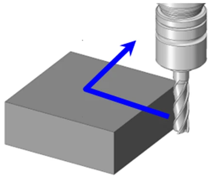
Consider the motion of a standard square end mill: it moves in a cylindrical manner, cutting material as it contacts the workpiece. When this motion occurs along a flat plane, it leaves behind a curved shape known as a “radius.”
Imagine moving an end mill in an L-shaped pattern against a block, as depicted in Figure 1.
The resulting shape after machining is shown in Figure 1-2. In machining, the outer corner of the folded portion does not form a sharp angle, as illustrated in (A). Instead, it adopts a radius equal to that of the cutting tool, as depicted in (B). This curved profile is what we refer to as a corner radius.
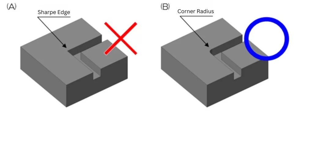
In machining, these corner radii are inevitable due to the rotation of the cutting tool. Especially in scenarios like the one depicted in Figure 1-2, where the corner is enclosed by three walls, a corner radius will always be present.
To eliminate corner radii, an alternative method called electrical discharge machining (EDM) can be employed. This technique involves creating an electrode in the inverse shape of the desired form and using electrical discharges to precisely melt away material. However, due to the expenses associated with electrode creation and the EDM process itself, this method is seldom utilized unless absolutely necessary.
Understanding the Impact of Corner Radius
To better understand how corner radii come into play, let’s explore some concrete examples.
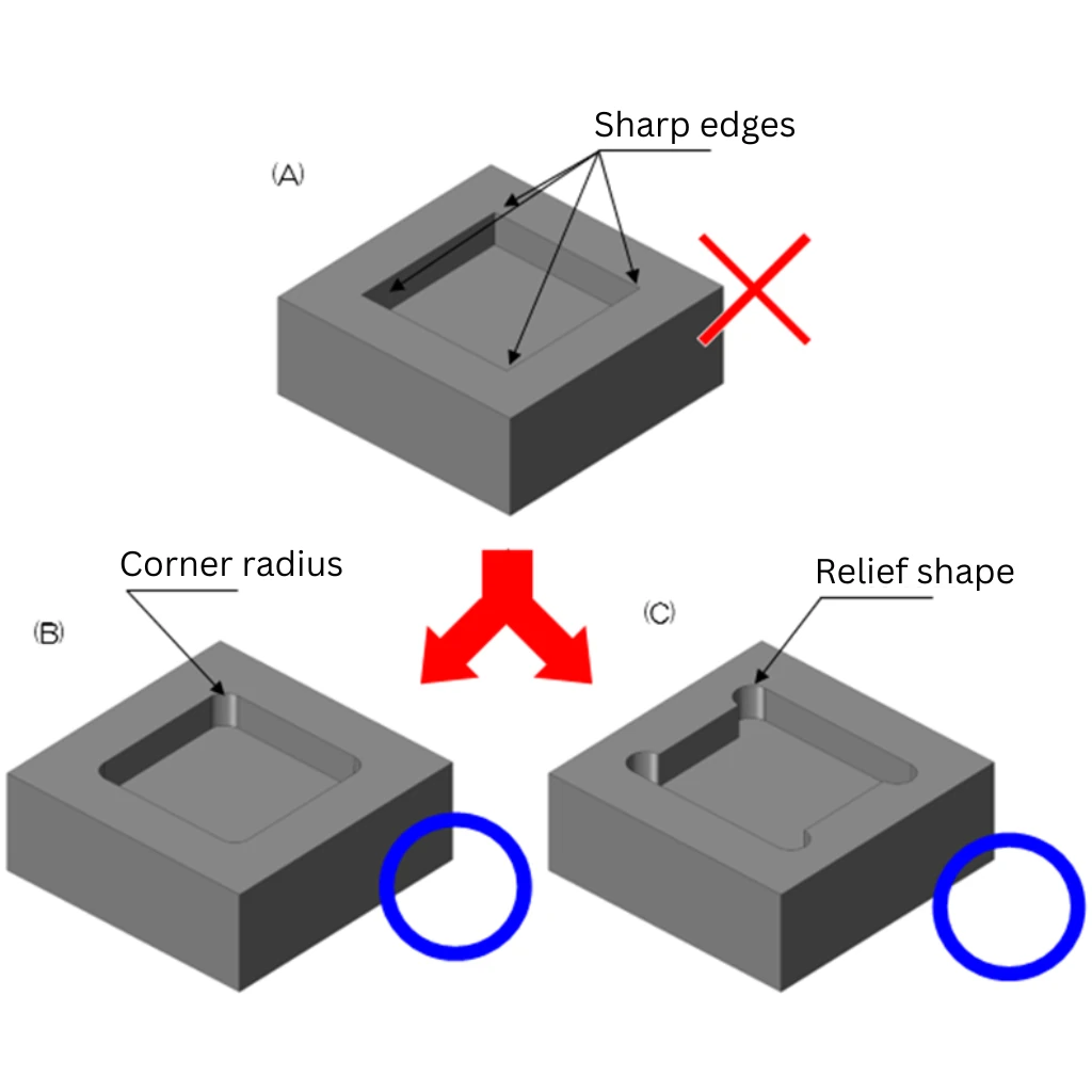
Figure 2-1 depicts a square pocket. Such pocket shapes are enclosed by three walls at all four corners. In these corner areas, corner radii are inevitably formed, as shown in (B), which is the common scenario.
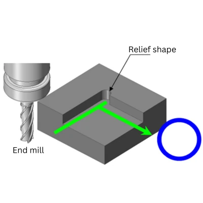
Another approach, as illustrated in (C), involves recessing the radii shape slightly outside the wall. This method may be employed when there is a specific object that needs to snugly fit inside the pocket. This intentional recessing of the shape to accommodate the object is also known as “relief shape.”
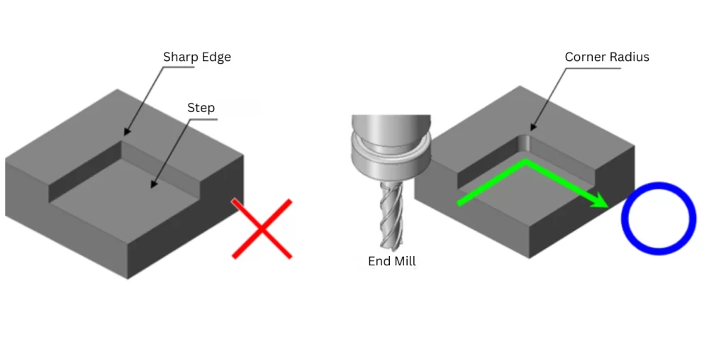
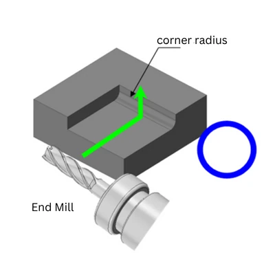
Consider the shape depicted in Figure 2-2: a corner enclosed by three walls, where a sharp angle cannot be formed. In actual machining, this scenario is often addressed by bringing the end mill down from above, resulting in corner radii on the folded portion, as shown in Figure 2-3.
Another possibility is machining from above, which could also introduce a recessed shape, as demonstrated in Figure 2-4.
Alternatively, one may consider the scenario depicted in Figure 2-5, where the end mill is brought in from the side of the block. Although less common due to factors like the length of the cutting tool, this method is still valid for introducing corner radii.
Relationship Between Corner Radius and Operational Adjustments
Now, let’s explore the connection between the orientation of corner radius placement and operational adjustments.
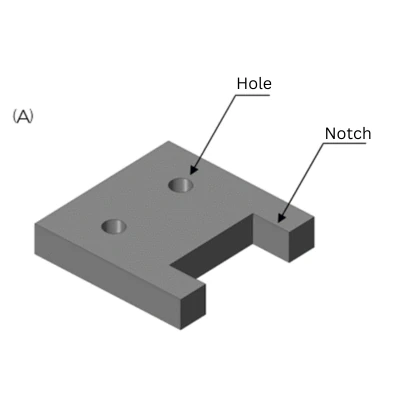
Consider Figure 3-1. Can a component with this configuration be machined, as discussed previously? This figure depicts a machined plate shape with two holes and a notch, without any corner radii on the notch.
The answer is, “Yes, it can be machined” If the shape doesn’t have walls enclosing it and the cutting tool can pass through, machining is feasible. However, this necessitates an operational adjustment.
When machining from different orientations, in fact, operational adjustments are necessary. This involves loosening the workpiece fixture, adjusting its orientation, re-securing it, setting the workpiece center, and so on. This process can be quite laborious, as you might imagine.
Range of Corner Radius
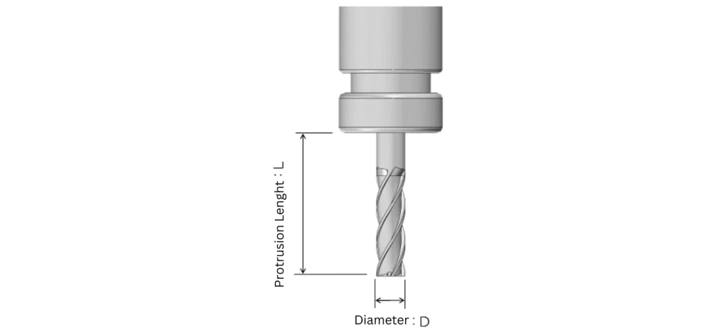
general, when contour machining with an end mill, a guideline of L / D ≤ 5 is recommended. While introducing a formula might seem abrupt, let’s break it down step by step.
In this formula, L represents the “protrusion length” [mm] of the cutting tool, which is the length of the end mill extending from the chuck holder. Meanwhile, D signifies the “diameter” [mm] of the end mill.
Conversely, if the protrusion length exceeds the diameter significantly, the cutting tool may experience vibrations. These vibrations can lead to rough surfaces, inaccurate dimensions, or even tool breakage during machining. Adhering to the guideline of L / D ≤ 5 helps mitigate such risks.
Of course, these criteria may vary depending on machining conditions, such as cutting tool speed and depth of cut, as well as material types. Nonetheless, it’s advisable to use this guideline as a rough estimate.
By treating the “depth of cut” in your design as equivalent to the “protrusion length,” you can calculate the acceptable size of radii for machining. Refer to the comparison of L / D in Figure 4-2.
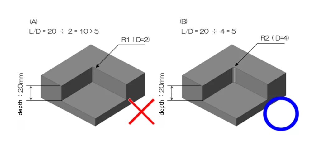
In the example(A) the corner radii are R1. With a notch depth of 20mm, L / D = 10, exceeding the threshold of 5. This indicates that the radii are too small for the notch depth, and thus, such a corner radius setting should be avoided.
On the other hand, the example (B) depicts R2, resulting in L / D = 5, making it a feasible corner radius setting.
Following this approach allows for a systematic assessment of the appropriateness of corner radius settings. However, it’s important to note that machining with an R0.1mm radius to cut a 1mm thickness is impractical, as it would require an end mill with a diameter of Φ0.2mm. (Although feasible in specific fields like mold machining or micro-machining.)
When uncertain, consulting with the machining workshop to determine the appropriate corner radius setting is recommended. Keeping these guidelines in mind can facilitate discussions and decisions regarding corner radius settings in machining drawings.
If no specific preferences are indicated, specifying “R3 or less” on the drawing allows the machining workshop to select the most suitable radius within the specified range.
Conclusion
In conclusion, understanding the significance of corner radii in machining is essential for designing mechanical components effectively. We’ve explored how corner radii are inevitable in certain shapes, emphasizing the importance of clearly specifying their locations on machining drawings to avoid misunderstandings and delays.
By following the principles presented in this article, designers can ensure the efficient production of mechanical components with optimal corner radii settings. Ultimately, integrating these insights into the design process can lead to smoother workflows, reduced costs, and enhanced precision in machining operations.