Deutsch
 Français
 Español
 Italiano
 Polski
BLOG » Understanding Technical Drawings for CNC Parts – Cycle 1
Understanding Technical Drawings for CNC Parts – Cycle 1
Technical drawings (also known as engineering drawings) are essential across various industries, serving as critical documents in design, manufacturing, quality control, and procurement. However, many professionals find them challenging to interpret, leading to miscommunication and inefficiencies. This series aims to demystify technical drawings by explaining their core principles and practical applications, ensuring they can be effectively understood and utilised in real-world scenarios.
Why Are Technical Drawings Important in CNC Machining?
In CNC machining, precision is paramount. A well-structured technical drawing ensures that a part is fabricated exactly as designed, avoiding costly errors and rework. By using standardised drawing conventions, manufacturers can accurately communicate design intent, tolerances, material specifications, and machining processes.
Basic Components of Technical Drawings
Understanding the core components of technical drawings helps streamline the production process and ensures all stakeholders are aligned.
1. Types of Lines in Technical Drawings
Lines are a fundamental aspect of technical drawings, each serving a distinct purpose to convey important manufacturing details. Solid lines define the visible edges of a part, giving machinists a clear outline of the component’s shape. Dashed lines, on the other hand, represent hidden features or internal structures that are not immediately visible from the exterior. Center lines are used to indicate symmetry and the positioning of critical features like holes, ensuring proper alignment during machining. Extension lines extend from parts to clarify dimensions, while break lines help shorten long objects in drawings without affecting accuracy. By using these different line types correctly, engineers can provide comprehensive manufacturing instructions with minimal ambiguity.
2. Views and Projections
Technical drawings employ different projection methods to represent 3D objects in an understandable 2D format. The most commonly used method is orthographic projection, which consists of multiple flat views—typically the front, top, and side—to fully define an object’s geometry. This approach eliminates distortion and provides a detailed breakdown of the part’s structure. In contrast, isometric drawings represent objects in a three-dimensional format without perspective distortion, making them useful for visualising how a part will look once manufactured. Another important view is the section view, which displays internal features that would otherwise remain hidden. By incorporating these projection methods, technical drawings offer a complete and precise representation of a component, ensuring accurate fabrication and assembly.
3. Dimensions and Measurements
Accurate dimensions are essential for translating a design into a manufacturable part. Dimension lines specify the exact size of a feature, providing critical information for CNC machining. These lines are complemented by extension lines, which connect dimension annotations to the relevant features in the drawing, preventing misinterpretation. Additionally, numerical values define precise measurements, tolerances, and allowances to ensure the part functions correctly and fits seamlessly with other components. The application of precise dimensions and measurements eliminates uncertainties, allowing machinists to produce parts that meet the intended design specifications with high accuracy.
4. Title Block
A title block contains essential information about the drawing, including:
- Part Name and Number: Helps with identification and inventory.
- Designer and Approval Signatures: Ensures accountability in the design process.
- Material Specifications: Specifies the material to be used for manufacturing.
- Scale: Defines whether the drawing is full-size, enlarged, or reduced.
- Standards Used (e.g., ISO 128): Ensures consistency in documentation.
Key Principles of Technical Drawings
1. Standardisation
Technical drawings follow established standards like ISO 128 and ASME Y14.5 to ensure that designs are universally understood, regardless of location or industry.
2. Accuracy
Every detail in a drawing must correctly represent the shape, size, and specifications of the part to prevent errors in machining.
3. Clarity
Well-structured drawings use proper line weights, labels, and symbols to ensure readability and ease of interpretation.
4. Completeness
A drawing should include all necessary details, such as material specifications, machining instructions, and surface finish requirements, leaving no room for ambiguity.
Common Elements in Technical Drawings
1. Symbols and Notations
Technical drawings use standard symbols to represent machining operations, surface finishes, and material properties. These symbols help CNC machinists quickly understand requirements without lengthy descriptions.
2. Scale
Drawings are created to scale to ensure accurate representation. Common scales include:
- 1:1 (Actual Size)
- 1:2 (Half Size)
- 2:1 (Double Size) This ensures that components are proportionally accurate during fabrication.
3. Tolerances
Tolerances define the allowable variation in a part’s dimensions. For CNC machining, tight tolerances are essential to ensure compatibility and performance. Tolerances are typically expressed as:
- Bilateral (+/-): Allows variation in both directions.
- Unilateral: Restricts variation to one direction.
- Geometric Dimensioning and Tolerancing (GD&T): Specifies exact conditions for form, orientation, and position.
How Technical Drawings Improve CNC Machining Efficiency
- Enhanced Communication – Engineers, designers, and machinists can work seamlessly using a universal drawing format.
- Error Reduction – Clear dimensions and tolerances prevent costly rework and material waste.
- Automation Readiness – Well-defined drawings integrate easily with CAD/CAM software for efficient CNC programming.
- Quality Control – Technical drawings serve as a reference for inspecting manufactured parts to ensure compliance with design specifications.
Cycle 1: The Fundamentals and Essence of Technical Drawings
How would you define a technical drawing? Many might describe it as a 2D projection of a part with dimensions clearly indicated for manufacturing guidance. While this is not incorrect, it does not fully encompass the broader role of technical drawings.
According to ISO 9001 (Quality Management System), technical drawings are classified as key “control documents.” As such, they require adherence to approval procedures and revision protocols, playing a crucial role in product development and manufacturing. This first cycle explores the essence of technical drawings and their various types.
Unlike general written information that can be digitised for convenience, technical drawings are more than a collection of dimensions. If dimensions alone were sufficient, 3D CAD models would replace drawings entirely. However, technical drawings convey much more, including tolerance specifications, surface roughness, material selection, machining notes, and inspection requirements. These elements ensure consistency in production and minimise variations in part size and shape. In essence, a technical drawing serves as a comprehensive specification document that translates design intent across various teams.
In addition to the design department, drawings are also used in the following departments for different purposes
| Department | Purpose of Technical Drawings |
|---|---|
| Production Management & Procurement | Assess machining conditions, deadlines, and costs to select the optimal manufacturing partner. |
| Manufacturing Engineering & Machining | Determine machining methods, select equipment, design processes, evaluate jigs, estimate machining costs, and optimise productivity. |
| Quality Assurance | Verify product specifications, reliability, safety, environmental considerations, assembly feasibility, and maintenance requirements. |
| Inspection | Select measurement tools and establish inspection procedures to ensure quality compliance. |
| Sales | Communicate with customers, discuss requirements, and justify cost estimates. |
| External Suppliers | Review drawings for quotations, manufacturing feasibility, inspection criteria, and delivery methods (e.g., returnable containers, cardboard packaging). |
Breaking Down Complex Drawings
For beginners, encountering a complex technical drawing for the first time can be overwhelming.
However, even the most intricate parts can be broken down into simpler geometric elements. After all, CAD software does not create designs independently—every component is the result of human thought and iterative problem-solving. When analysed correctly, most complex parts are simply combinations of basic shapes.
Many terms used in drafting are often misunderstood. The table below provides clear definitions for these terms
Table 1-2: Common Technical Drawing Terms
| Term | Definition |
|---|---|
| Planning Drawing | A drawing that represents the design intent and plan. |
| Installation Drawing | A drawing that provides information necessary for installing an item by depicting its general shape and its relationship with associated structures or related items. |
| General Appearance Drawing | A drawing that shows the external shape, overall dimensions, and mass of an object, required for determining packaging, transport, and installation conditions. |
| Development Drawing | A drawing that unfolds the surfaces of an object onto a plane. |
| Part Drawing | A drawing that contains all necessary information to define a single, indivisible part. |
| Material Drawing | A drawing that shows the pre-machined state of a mechanical part, such as a casting or forging. |
| Assembly Drawing | A drawing that depicts the relative positioning and configuration of assembled parts. |
| Single-Part, Single-Sheet Drawing | A drawing where a single part or assembly is depicted on one sheet of drafting paper. |
| Single-Part, Multi-Sheet Drawing | A drawing where a single part or assembly is depicted across multiple sheets of drafting paper. |
| Multi-Part, Single-Sheet Drawing | A drawing where multiple parts or assemblies are depicted on a single sheet of drafting paper. |
| Tracing Drawing | The act of copying a drawing onto tracing paper or a similar medium. |
| Drawing Inspection | The act of reviewing and verifying a drawing. |
| Drawing Number | A unique number assigned to each drawing sheet. |
| Drawing Issuance | The act of issuing a registered drawing. |
| Copy Drawing | A drawing created as a reproduction of the original, either by duplication or as a hard or soft copy from digital data. |
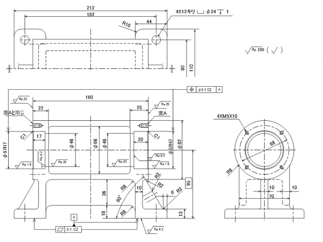
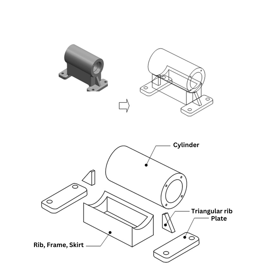
Even complex and intricate component shapes can be broken down into a collection of simple shapes. This is because CAD design is carried out by humans, not by computers that autonomously create unknown shapes. Even if a designer spends days refining a shape through trial and error, it is ultimately just an assembly of simple shapes.
By breaking down the 3D shape derived from a drawing into its individual elements, it becomes clear that it is made up of a collection of simple shapes (Figure 1-2).
A drawing is a technical document that concisely summarises these shape elements, using various projection techniques and dimensioning methods in accordance with established rules to enhance understanding.
General Rules Before Creating a Drawing
The following describes the rules before beginning a projection drawing.
Paper Size
The size of the paper used in mechanical drafting, as well as its border lines and title block, are specified as follows.
Although this is the digital data era, paper drawings remain essential in manufacturing, particularly for inspection and on-site work, where dimensions may be written directly onto the paper or overlaid onto physical components for comparison. The demand for paper drawings remains high.
The primary selection criterion is A-series paper sizes (five types: A0 to A4) (Table 1-3).
paper sizes (five types: A0 to A4) (Table 1-3).
| Designation | Short Edge × Long Edge (mm) |
|---|---|
| A0 | 841 × 1189 |
| A1 | 594 × 841 |
| A2 | 420 × 594 |
| A3 | 297 × 420 |
| A4 | 210 × 297 |
Standard copier paper is A4, and two sheets of A4 side by side form A3. The area doubles sequentially up to A0, the largest size.
Border Lines and Margins
To prevent damage such as tearing along the edges of printed paper, a border line must be drawn to clearly define the drawing area.
- For A0 and A1, the border line should be set 20 mm from each edge.
- For A2 to A4, the border line should be 10 mm from each edge.
- If a binding margin is required, an additional 20 mm should be left on the left edge of A2 to A4.
Although microfilming is no longer necessary for CAD data storage, a remnant of the practice persists: a bold centre mark is placed at the middle of each edge of the drawing for alignment during copying
Title Block
The title block is a designated section of a drawing for recording essential management information such as drawing number, part name, material, and responsible personnel. It functions as the index of a drawing.
The title block is typically placed in the bottom right corner of the drawing. However, if overlapping with drawing content, it may be positioned in the top right corner, aligned with the drawing orientation (Figure 1-5).
Summary
This section has highlighted the crucial role of drawings as the sole medium for conveying design information from the designer to the next stage of manufacturing, translating intangible ideas into tangible components.
Additionally, we explored basic drafting terminology and the rules that apply before creating a drawing.