Deutsch
 Français
 Español
 Italiano
 Polski
BLOG » Understanding Mechanical Mechanisms – Types and How They Work
Understanding Mechanical Mechanisms – Types and How They Work
In the world of mechanical design and automation, understanding mechanical mechanisms is fundamental to building efficient, reliable machines. Whether you’re developing pick-and-place units or designing complex industrial systems, selecting the right motion conversion method can make all the difference in performance, cost, and durability. In this article, we step back from the specifics of component design and focus instead on core mechanical mechanisms that power machines across industries—from motion control and indexing to force transmission and synchronised movement. Rather than cover everything in one go, we’ll explore essential examples that show how these mechanisms work and why they matter.
What Are Mechanical Mechanisms?
Mechanical mechanisms are systems or assemblies that convert motion or transmit force in a controlled and repeatable way. They form the basis of motion in all types of mechanical equipment, whether it’s turning rotary motion into linear displacement or converting continuous motion into intermittent steps. Mechanisms can include cams, linkages, gears, screws, and other components that define how energy is transferred and movement is executed. Mastering the use of these mechanisms enables engineers to design drawings for machines that are more precise, energy-efficient, and optimised for a wide variety of applications.
Types of Mechanical Mechanisms
There are two drive sources for mechanical mechanisms, rotary and linear. Based on the motion of the power source and how it’s converted, we can categorise common mechanisms as follows. Each has its own strengths and weaknesses.
Table: Categories of Mechanical Mechanisms
| Drive Source | No. | Motion Type | Conversion Mechanism | Example |
|---|---|---|---|---|
| Rotary | 1 | Linear | Ball Screw Timing Belt Rack & Pinion | Single-axis actuator |
| 2 | Intermittent | Cam Geneva Mechanism | Indexing device | |
| 3 | Reciprocating | Mechanical Cam Electronic Cam Link Screw (lead or ball) | Servo motor, Wiper, Table lifter, Scissor jack, Shift pedal | |
| 4 | Synchronous | Line Shaft | Conveyor, packing equipment | |
| 5 | Force Boost | Pulley | Crane | |
| 6 | Rotation Hold | Flywheel | Engine, toy, sewing machine | |
| Linear | 7 | Rotary | Slider Crank Rotary Actuator | Reciprocating engine |
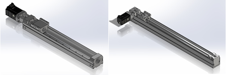
1. Converting Rotary Motion to Linear Motion
This is one of the most commonly used conversions in automation design. The rotary motion from a servo motor or stepper motor is converted into linear motion using ball screws, timing belts, or rack-and-pinion systems.
Comparison of Linear Motion Conversion Mechanisms
| Mechanism | Advantages | Disadvantages |
|---|---|---|
| Ball Screw | – High positional accuracy – High speed and high acceleration possible | – Not ideal for long strokes – Noisy (ball rolling sound) – Expensive |
| Timing Belt | – High-speed transport – Supports long strokes – Low noise, low cost – No lubrication needed | – Lower accuracy depending on tooth profile – Not suitable for high acceleration (belt stretch) |
| Rack & Pinion | – High speed – Long stroke capability – Supports high acceleration and deceleration | – Requires lubrication – Noisy – Generates wear particles |
Note: Motor mounting orientation differs between ball screw and timing belt actuators, so this must be considered during design. Linear servo actuators are also gaining popularity. They offer high precision, low noise, and high speed but are more expensive and reliant on rare earth magnets for the stator.
See below for the general guidelines for mechanism selection:
- Choose ball screws for high accuracy
- Choose timing belts for low cost
- Choose timing belts or rack & pinion for long-stroke applications
2. Converting Rotary to Intermittent Motion
This is widely used in indexing mechanisms. Cams or Geneva mechanisms convert the continuous rotation of a motor into intermittent output motion.
Cam-based indexers are popular in automation because the cam profile defines smooth movement, the indexing angle, and the stop duration. Even while the input shaft rotates continuously, the output can be held stationary for part of the cycle.
Geneva mechanisms are simpler and more cost-effective but offer less smooth motion.
Comparison of Intermittent Motion Mechanisms
| Mechanism | Advantages | Disadvantages |
|---|---|---|
| Cam | – Smooth motion via profile control | – Complex cam shape increases machining costs |
| Geneva Mechanism | – Simple shape – Low cost | – Cannot achieve as smooth motion as a cam |
Note: Indexing devices must be specified carefully (e.g. acceleration ratio) early in the design, as later changes aren’t easy. That said, they’re simple and reliable. Zero-backlash types also exist for servo motor integration.
Mechanisms That Convert Direction and Range of Motion
Linkages
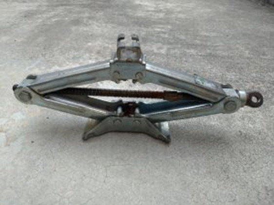
Linkages are mechanical systems used to convert motion direction and movement range. Commonly found in various applications, link mechanisms transform rotary motion into reciprocating motion (as in windscreen wipers), stabilise movement (as in table lifters), or convert force and stroke (as in pantograph jacks).
Although textbooks often introduce complex four-bar linkage formulas and velocity equations, in typical engineering design, it’s more practical to focus on two key aspects:
- How the motion behaves, and
- The mechanical advantage (lever ratio).
Motion Conversion Mechanisms – Advantages and Disadvantages
Lorem ipsum dolor sit amet, consectetur adipiscing elit. Ut elit tellus, luctus nec ullamcorper mattis, pulvinar dapibus leo.
For example, in a car’s windscreen wiper, the motor drives a short linkage arm that transforms rotary motion into the back-and-forth sweeping motion. The motor-side link is shorter than the wiper arm side, enabling the rotary-to-reciprocating conversion.
Similarly, pantograph jacks used for tyre changes raise a car by deforming a scissor-like structure when the screw is turned. The formula governing this mechanism is F = T * tan(θ).
Motorcycle gear shifters also utilise linkages. Pressing the L-shaped pedal (①) causes part ② to move linearly. This, in turn, makes part ③ oscillate, changing gears via a shaft connected to the transmission.
Linkages are simple enough to prototype using cardboard models or simulate with 3D CAD software. CAD also allows for stress analysis on individual components under operation.
Cam Mechanisms
Cams come in various forms, such as plate cams and groove cams. The plate cam is the most commonly used type. Examples include:
- Engine intake/exhaust valve actuation (plate cams)
- Indexing mechanisms (groove cams)
Every cam requires a follower (the component moved by the cam). The follower is typically spring-loaded to stay in contact with the cam profile. At high rotation speeds, the spring may fail to maintain contact, leading to “surging”—a state where the follower lifts off the cam surface. This must be accounted for in cam design.
Mechanical cams were widely used in machines requiring fixed, repeatable motion. However, due to the growing demand for high-mix, low-volume production, mechanical cams have seen reduced use in favour of servo motors with electronic cam (e-cam) functionality.
Using an electronic cam, the controller creates a virtual cam axis within a program. The servo motor linked as the follower can replicate traditional cam movements. The cam profile is easily reprogrammable, making this approach highly flexible for frequent changeovers—albeit with higher equipment costs.
4.Mechanism for Synchronising Rotary Motion
The line shaft mechanism is used to synchronise long conveyor systems using a single motor. Although now rare due to improved motor availability and lower costs, it remains in use in certain conveyor applications.
In this system, a motor drives a long shaft, which transfers motion via round belts (small conveyors) or miter gearboxes (larger conveyors). For segmented conveyors, couplings extend the shaft to ensure all conveyors run from a single motor.
Benefits:
- Simplified control and maintenance
- Fewer electrical components, reducing failure risk
Drawbacks:
- Minimal flexibility for later system modifications
Historically, systems like bottle case packers combined cams with line shafts to automate tasks like alignment, handling, packing, and discharge.
5. Mechanism to Multiply Input Force
A classic force multiplication system can be seen in crane hook mechanisms. One side of the cable is fixed; the folded cable runs through pulleys and connects to the winch. The load is suspended via a pulley in the centre, meaning the required winch force is halved.
This is the movable pulley principle. The fixed pulley (left in the diagram) transmits the full weight, requiring 98 N of force. The movable pulley (right) supports the load through both the ceiling and the pulling force, requiring only 49 N.
| Mechanism | Advantages | Disadvantages |
|---|---|---|
| Pulley | – Changes both force direction and magnitude. | – Tension must always be applied, or the cable may come off. |
6. Mechanism to Stabilise Rotary Motion
A flywheel (or “inertia wheel”) helps maintain consistent rotational speed. In servo motor design, timing pulleys and gears are treated as flywheel equivalents due to their inertia.
Mechanically, a flywheel stores rotational energy. A typical use case is in engine crankshafts. Since energy from combustion is lost due to friction, and the crank must rotate twice before the next explosion in a 4-stroke engine, the flywheel helps retain this rotational momentum.
Children’s spinning toys also demonstrate this principle—they maintain motion after a push thanks to their internal flywheel effect.
There are two important points to consider to stabilise rotary motion:
- The motion is too heavy → hard to start or sluggish operation
- The motion is too light → cannot maintain rotational energy
Flywheel Mechanism – Advantages and Disadvantages
| Mechanism | Advantages | Disadvantages |
|---|---|---|
| Flywheel | – Maintains rotation without active control. | – Can cause sluggish response due to its weight/inertia. |
7. Converting Linear to Rotary Motion
Mechanisms such as the slider-crank and rack and pinion convert linear motion into rotary motion—and vice versa.
In a typical engine, the piston moves down due to combustion. This motion is transferred via a connecting rod to the crankshaft, which converts it into rotation. The reverse is true in press machines: the crank rotates to drive a press head downward.
Rack and pinion systems are used in devices like pneumatic rotary actuators and stage rotation mechanisms. One key advantage is the potential to generate high torque. Using two racks and one pinion also reduces bending stress on the rotational axis.
Motion Conversion Mechanisms – Advantages and Disadvantages
| Mechanism | Advantages | Disadvantages |
|---|---|---|
| Slider-Crank | – Simple design; converts linear to rotary (and vice versa). | – Non-uniform output speed when input is at a constant rate. |
| Rack & Pinion | – Enables high torque; commercially available components. | – Limited to specific stroke or rotation angle. |
Summary
In summary, motion conversion mechanisms—whether linkages, cams, pulleys, or flywheels—are fundamental to countless mechanical systems. Each type offers unique advantages and trade-offs, and understanding their behaviour in real-world applications is key to effective design. By focusing on practical performance rather than textbook formulas, engineers can create robust, efficient mechanisms suited to today’s diverse manufacturing needs. Familiarity with these systems not only improves design quality but also fosters innovation in developing smarter motion solutions.
What is meviy?
meviy is an AI-powered on-demand manufacturing platform developed by MISUMI. It allows engineers to upload 3D CAD models and receive instant quotations, automatic manufacturability analysis, and lead time estimates. Supporting processes like CNC machining, sheet metal fabrication, meviy streamlines procurement, reduces communication loops, and accelerates product development. Its AI capabilities also enable part recognition, interactive design editing, and compatibility with a wide range of materials—making it a smart, fast, and reliable tool for today’s engineering teams.