Deutsch
 Français
 Español
 Italiano
 Polski
BLOG » A Guide to CNC Machining Tolerances
A Guide to CNC Machining Tolerances
In CNC machining, tolerances play a crucial role in ensuring that parts meet functional and assembly requirements. Tolerance defines the allowable variation in dimensions, affecting the accuracy and performance of the final component. Understanding tolerances is essential for engineers, designers, and manufacturers to optimise production while maintaining cost-effectiveness.
What Are Tolerances in CNC Machining?
Tolerances specify the permissible deviation from a nominal dimension, ensuring that a part fits within the required mechanical and functional constraints. These deviations are usually measured in microns (µm) or millimetres (mm) and depend on factors such as material properties, machining processes, and design requirements. These specifications are crucial in technical drawings, where engineers indicate dimensional allowances using standard notation. By setting precise tolerances, manufacturers can balance cost, material efficiency, and performance, ensuring that CNC-machined parts meet industry standards and functional requirements.
As explained, tolerances are used to control how much a manufactured part can deviate from its nominal dimensions without affecting functionality. These tolerances are crucial for ensuring interchangeability, fit, function, and manufacturability.
Here are the main types of tolerances commonly used in parts design:
1. Dimensional Tolerances
apply to the size of features such as lengths, diameters, thicknesses, etc.
- Linear tolerances: e.g., 50 ± 0.1 mm
- Angular tolerances: e.g., 90° ± 0.5°
- Often defined using ISO 2768-1 for general tolerances when not explicitly stated.
2. Geometrical Tolerances (GD&T)
Defined by BS 8888 (UK standard that aligns with ISO 1101)
These control shape, orientation, and position of features beyond just size.
Main types:
- Form tolerances
- Straightness
- Flatness
- Circularity
- Cylindricity
- Orientation tolerances
- Perpendicularity
- Parallelism
- Angularity
- Location tolerances
- Position
- Concentricity
- Symmetry
- Runout tolerances
- Circular runout
- Total runout
Each has a specific symbol used in a feature control frame on the technical drawing.
3. Surface Texture Tolerances
- Specify the roughness or surface finish of a part.
- Indicated using symbols like Ra (roughness average).
- Governed by BS EN ISO 1302.
4. Fits and Limits Tolerances (Hole/Shaft System)
- Specifies how tightly or loosely two mating parts fit together.
- Governed by BS EN ISO 286 (previously BS 4500).
- Uses tolerance grades (IT01–IT16) and letter codes for holes (H, G, etc.) and shafts (h, g, etc.)
- E.g., H7/g6 = sliding fit
Types of fits:
- Clearance fit
- Transition fit
- Interference fit
5. Positional and Datum-Based Tolerances
- Control where features must be located in relation to each other or to a reference.
- Often used with GD&T.
Summary Table
| Type | Controlled Feature | Example / Standard |
|---|---|---|
| Dimensional | Size (length, diameter) | ISO 2768-1, BS 8888 |
| Geometrical (GD&T) | Shape, position | ISO 1101, BS 8888 |
| Surface Texture | Finish, roughness | ISO 1302 |
| Limits and Fits | Mating parts | ISO 286, BS EN ISO 286 |
| Positional | Relative location | GD&T Feature control frame |
Key Terminology in Size Tolerances
Misunderstanding tolerance-related terms can lead to design errors. To ensure accuracy, we’ll provide the below definitions based on international standards:
| Term | Definition |
|---|---|
| Size Geometry | The geometric shape defined by length or angle measurements. |
| Nominal Size | The theoretically perfect dimension as shown in a drawing. |
| Tolerance Limits | The maximum and minimum allowable size for a feature. |
| Upper Limit | The largest permissible size. |
| Lower Limit | The smallest permissible size. |
| Tolerance Value | The difference between the upper and lower limits. |
| Upper Deviation | The deviation from the nominal size to the upper limit. |
| Lower Deviation | The deviation from the nominal size to the lower limit. |
| Tolerance Class | A combination of fundamental tolerances and basic size grades. |
Why Understanding Tolerances Matters
Selecting the correct tolerance is essential for balancing precision, manufacturability, and cost. Overly tight tolerances may increase machining complexity and costs, while overly loose tolerances can lead to assembly issues. By following industry standards and defining tolerances correctly, engineers can improve production efficiency and ensure part compatibility.
General Tolerances: The Standard for Dimensional Variation
When a dimension is specified with a ±0.1 tolerance, manufacturers pay close attention to variation. But what happens when a dimension is given without a tolerance? How do we determine the acceptable range of variation?
The answer lies in general tolerances, also known as standard tolerances or ordinary permissible deviations in design and manufacturing. These are predefined tolerances that apply when explicit tolerances are not specified, helping to keep technical drawings clean and uncluttered.
Understanding General Tolerances
If a dimension is shown without a tolerance, standard practice assumes an equal tolerance range on both the plus and minus sides, centred around the nominal dimension. This means that whether a part is produced slightly larger or smaller, as long as it stays within the permitted range, it remains acceptable.
The specific values of general tolerances vary depending on the manufacturing method. Below, we focus on the common general tolerances for machining processes, based on standards.
Table 5-2 General tolerances for length dimensions excluding chamfering (JIS B 0405-1991 ~ In the case of cutting)
| Tolerance Grade | Classification of Standard Dimensions | 0.5 to 3 | Over 3 ≤ 6 | Over 6 ≤ 30 | Over 30 ≤ 120 | Over 120 < 400 | Over 400 < 1000 | Over 1000 < 2000 | Over 2000 < 4000 |
|---|---|---|---|---|---|---|---|---|---|
| Tolerance | Fine grade | ±0.05 | ±0.05 | ±0.1 | ±0.15 | ±0.2 | ±0.3 | ±0.5 | – |
| Intermediate | ±0.1 | ±0.1 | ±0.2 | ±0.3 | ±0.5 | ±0.8 | ±1.2 | ±2 | |
| Coarse grade | ±0.2 | ±0.3 | ±0.5 | ±0.8 | ±1.2 | ±2 | ±3 | ±4 | |
| Very coarse | – | ±0.5 | ±1 | ±1.5 | ±2.5 | ±4 | ±6 | ±8 |
Table 5-3 General tolerance of chamfer length (JIS B 0405-1991 ~ For cutting)
| Tolerance Class | Classification of Standard Dimensions | ||
| Explanation | 0.5 or higher 3 or less | Above 3 6 or less | Above 6 |
| Tolerance | |||
| Fine Grade | ±0.2 | ±0.5 | ±1 |
| Intermediate | |||
| Coarse Grade | ±0.4 | ±1 | ±2 |
Table 5-4 General tolerances for angle dimensions (JIS B 0405-1991 – for cutting)
| Tolerance Class | The length of the shorter side of the angle in question | ||||
| explanation | 10 or less | Above 10 | Over 50 | Above 120 | Above 400 |
| Under 50 | Under 120 | Under 400 | |||
| Tolerance | |||||
| Fine grade | ±1° | ±30′ | ±20′ | ±10′ | ±5′ |
| Intermediate | |||||
| Coarse grade | ±1°30′ | ±1° | ±30′ | ±15′ | ±10′ |
| Very coarse | ±3° | ±2° | ±1° | ±30′ | ±20′ |
Machining Tolerance Grades
General tolerances for machining are classified into four grades:
- Fine Grade (f) – High precision
- Medium Grade (m) – Standard precision
- Coarse Grade (c) – Lower precision
- Very Coarse Grade (v) – Rough machining
How to Specify Dimensional Tolerances Correctly
In cases where general tolerances are insufficient, tighter tolerances must be specified to meet functional and assembly requirements. However, unnecessarily strict tolerances increase machining costs exponentially, as fewer manufacturers can achieve extreme precision.
1. How to Indicate Size Tolerances
For size tolerances, the allowable deviation is written next to the nominal dimension. If the upper and lower deviations are not symmetrical, they are written stacked above and below the nominal value.
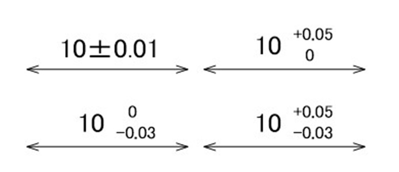
Size tolerance does not necessarily have to be evenly distributed around the nominal dimension. It is possible to bias the tolerance towards either the positive or negative side (commonly referred to as unilateral tolerance in design settings).
In this way, designers express their design intent on drawings as targeting the median, upper, or lower range relative to the nominal dimension. However, it is important to remember that machinists typically aim for the midpoint of the allowable tolerance range during manufacturing.
There are no strict regulations on the font size for tolerance values. According to JIS examples, tolerance values are written in the same font size as the dimension numbers. As long as the text is legible, the default settings in CAD software should be sufficient.
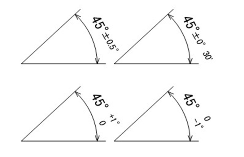
2. Indicating Angular Size Tolerances
The notation for angular size tolerance follows the same format as size tolerance. However, angular dimensions require unit symbols, and the sexagesimal (base-60) system is generally used, represented in degrees (°), minutes (′), and seconds (″).
How should minutes (′) and seconds (″) be interpreted?
This works similarly to a clock: when 60 minutes pass, they form 1 degree, rolling over to the next unit. This counting method is known as the sexagesimal system.
In contrast, regular numerical notation follows the decimal system, where 9 increments to 10. The following table provides a conversion between angular minutes (′) in the base-60 system and decimal degrees.
Angle Conversion Table (Minutes to Decimal Degrees)
| Minutes (′) | Decimal Degrees | Minutes (′) | Decimal Degrees | Minutes (′) | Decimal Degrees | Minutes (′) | Decimal Degrees |
| 1′ | 0.0167° | 16′ | 0.2667° | 31′ | 0.5167° | 46′ | 0.7667° |
| 2′ | 0.0333° | 17′ | 0.2833° | 32′ | 0.5333° | 47′ | 0.7833° |
| 3′ | 0.0500° | 18′ | 0.3000° | 33′ | 0.5500° | 48′ | 0.8000° |
| 4′ | 0.0667° | 19′ | 0.3167° | 34′ | 0.5667° | 49′ | 0.8167° |
| 5′ | 0.0833° | 20′ | 0.3333° | 35′ | 0.5833° | 50′ | 0.8333° |
| 6′ | 0.1000° | 21′ | 0.3500° | 36′ | 0.6000° | 51′ | 0.8500° |
| 7′ | 0.1167° | 22′ | 0.3667° | 37′ | 0.6167° | 52′ | 0.8667° |
| 8′ | 0.1333° | 23′ | 0.3833° | 38′ | 0.6333° | 53′ | 0.8833° |
| 9′ | 0.1500° | 24′ | 0.4000° | 39′ | 0.6500° | 54′ | 0.9000° |
| 10′ | 0.1667° | 25′ | 0.4167° | 40′ | 0.6667° | 55′ | 0.9167° |
| 11′ | 0.1833° | 26′ | 0.4333° | 41′ | 0.6833° | 56′ | 0.9333° |
| 12′ | 0.2000° | 27′ | 0.4500° | 42′ | 0.7000° | 57′ | 0.9500° |
| 13′ | 0.2167° | 28′ | 0.4667° | 43′ | 0.7167° | 58′ | 0.9667° |
| 14′ | 0.2333° | 29′ | 0.4833° | 44′ | 0.7333° | 59′ | 0.9833° |
| 15′ | 0.2500° | 30′ | 0.5000° | 45′ | 0.7500° | 60′ | 1.0000° |
When specifying angular tolerances, the choice between decimal notation and sexagesimal notation is typically up to the designer’s preference.
Accumulation of Tolerances
To examine how dimensioning methods affect variation, serial dimensioning and parallel dimensioning have been illustrated using general tolerances (medium grade) (see Figures 5-3 and 5-4).
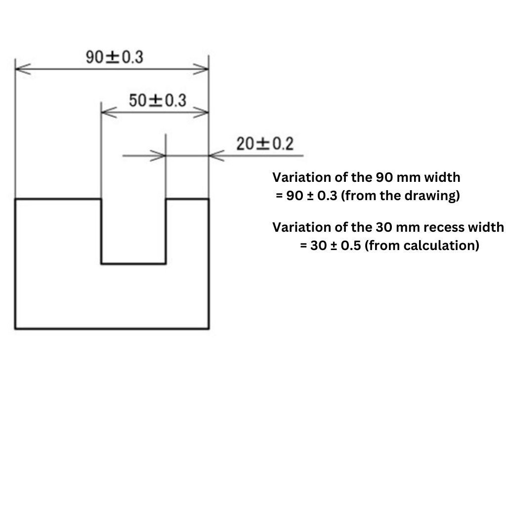
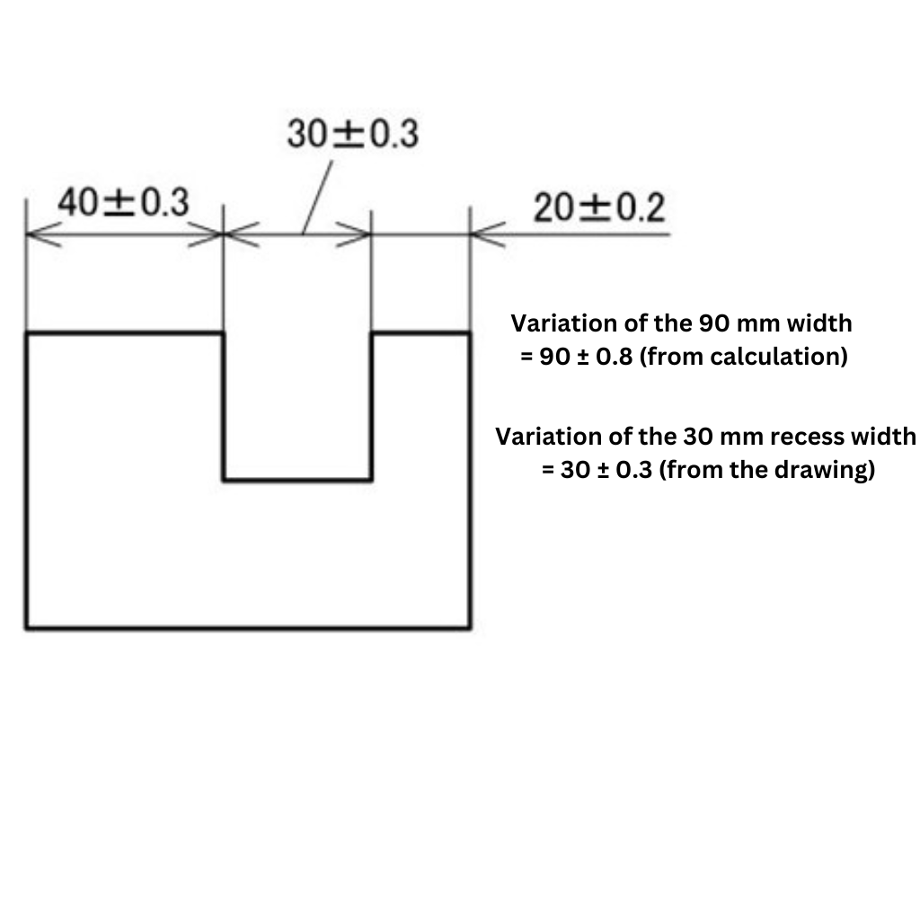
Let’s examine two key dimensions—total width (90 mm) and groove width (30 mm)—to assess the variations in dimensions after machining.
Total Width
- Sequential Dimensioning: 90 ± 0.8 mm
- Cumulative Tolerance Calculation: [±0.3] + [±0.3] + [±0.2] = ±0.8
- Parallel Dimensioning: 90 ± 0.3 mm (directly readable from the dimension notation)
From this, we can see that the dimensional variation in sequential dimensioning is 0.5 mm larger than in parallel dimensioning.
Groove Width
- Sequential Dimensioning: 30 ± 0.3 mm (directly readable from the dimension notation)
- Parallel Dimensioning: 30 ± 0.5 mm
- Cumulative Tolerance Calculation: [±0.3] + [±0.2] = ±0.5
Note: While the base dimension is determined through subtraction, tolerances are cumulative and must be added. As a result, the groove width variation in parallel dimensioning is 0.2 mm larger than in sequential dimensioning.
This example highlights that both dimensioning methods have advantages and disadvantages depending on the specific part feature.
However, a general rule applies:
- Critical functional dimensions should always be directly specified to minimise variation.
- Avoid relying on additive or subtractive calculations for essential dimensions.
In other words, if the exact sizes of the protrusion and groove are more critical than the total length of 90 mm, the dimensioning method shown in Figure 5-3 is preferable. Conversely, if the total length of 90 mm or the position of the groove from the right edge is more important than the groove width of 30 mm, the dimensioning method in Figure 5-4 is more suitable.
Understanding Fit Types: Essential Knowledge for Precision Machining
When assembling components, ensuring precise alignment or controlled movement is essential. This is where “fits“ come into play.
A fit refers to the dimensional relationship between a hole and a shaft before assembly. There are three primary types, each suited to different applications:
- Clearance Fit: Used for positioning stationary components or allowing movement in rotating/sliding parts.
- Interference Fit: Used when components need to be press-fitted and secured permanently.
- Transition Fit: A variable fit that may behave as either a clearance or interference fit, depending on tolerance variations. Because of this unpredictability, designers rarely prefer transition fits unless absolutely necessary.
How to Specify Fits in Technical Drawings
Fit classifications use a standardised notation system, combining an uppercase or lowercase letter with a numerical grade to define tolerance classes. This notation is internationally recognised.
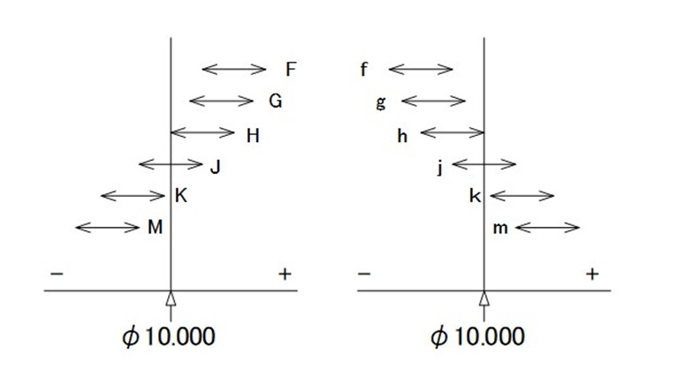
- For holes (internal features like grooves), an uppercase letter is used → Example: φ10H7
- For shafts (external features like protrusions), a lowercase letter is used → Example: φ10h7
The alphabetic symbol represents the location of the tolerance zone relative to the nominal size (whether it is biased towards the positive or negative side). The below image provides a visual representation of this concept.
Summary
In this session, we explored general tolerances, size tolerances, and fit tolerance class symbols. These symbols follow globally recognised standards, making them universally applicable in international manufacturing. As a designer, it’s crucial to keep the following points in mind:
- Understand the presence and values of general tolerances before assigning any specific tolerance.
- Tolerances related to size are referred to as “size tolerances.”
- Overly strict tolerances increase machining difficulty, leading to higher costs.
- The arrangement of dimensions can distinguish between critical and non-critical features.
- For high-precision fits, tolerance classes should be expressed using standard notation.