Deutsch
 Français
 Español
 Italiano
 Polski
BLOG » Sheet Metal Design Guide: The Role of Drawings in Sheet Metal Fabrication
Sheet Metal Design Guide: The Role of Drawings in Sheet Metal Fabrication
In sheet metal fabrication, precise and well-structured drawings are essential for ensuring smooth production and accurate communication between designers and manufacturers. A well-prepared drawing not only conveys critical details like dimensions, tolerances, and materials but also helps prevent costly errors and manufacturing delays. In this guide, we will explore the fundamentals of sheet metal design including drawings, such as essential symbols, best practices for creating clear and effective designs, and common fabrication challenges—along with practical solutions to overcome them.

What Are Sheet Metals?
Sheet metals are thin, flat pieces of metal that are widely used across various industries due to their versatility, durability, and ease of fabrication. They are typically made from materials such as steel, aluminium, , resin, and stainless steel, with thicknesses ranging from a fraction of a millimetre to several millimetres. Sheet metals are commonly used in applications such as automotive parts, industrial machinery, electronics, construction, and aerospace components.
What Is Sheet Metal Fabrication?
Sheet metal fabrication is the process of transforming raw sheet metal into finished components or structures through cutting, bending, punching, welding, and assembling. This manufacturing process is essential for creating custom metal parts with precise dimensions and complex geometries. Modern fabrication techniques often involve CNC machining, laser cutting, and press brake bending, ensuring high precision and efficiency. Sheet metal fabrication plays a crucial role in industries that require lightweight, durable, and cost-effective metal solutions.
The Sheet Metal Fabrication Process
Conceptual Design
The design process of sheet metal products begins with conceptualisation, where the required functionality and ideal shape of the part are determined. Initial sketches help designers communicate their ideas with stakeholders. Sheet metal parts serve various purposes, such as protective covers, structural frames, or airflow guides.
CAD Modelling
Most design teams use 3D CAD software to create precise models. This stage involves selecting materials, determining sheet thickness, and finalising shapes before generating 2D technical drawings from the 3D models.
Quotation and Manufacturing Review
Once the drawings are complete, the feasibility of production is assessed. If no issues arise, manufacturing proceeds. However, adjustments to tolerances, shapes, costs, or lead times may be required. For example, opting for an in-stock material can reduce production time.
Fabrication
After finalising the design and agreeing on all conditions, fabrication begins. The process often involves laser cutting, press brake bending, and welding.
Inspection and Delivery
Before shipment, parts are measured to ensure they meet drawing specifications. Complex shapes may require 3D measuring instruments for verification. If all measurements fall within tolerance, the parts are approved for delivery.
Sheet Metals Design Guide: Key Considerations
While dimensions and tolerances are essential, other factors also influence quality of sheet metal drawing. Here are key considerations:
Include a Title Block
A title block contains vital information such as part number, name, material, thickness, and tolerance grade. Each company may have slightly different formats.
Specify Reference Dimensions
Accurate reference points (datums) ensure consistency and ease of measurement, even for complex geometries.
Consolidate Dimensions in the Front View
To enhance readability, consolidate as many dimensions as possible in the front view rather than scattering them across multiple projections.
Address Burrs
Sheet metal cutting often produces burrs. Drawings should indicate whether burr removal is required and specify the acceptable burr height.
Use Feasible Tolerances
Tolerances should align with manufacturing capabilities. Typical sheet metal fabrication tolerances are:
- Hole-to-hole distance: ±0.05mm
- Hole-to-bend distance: ±0.15mm
Consider Bend Deformation
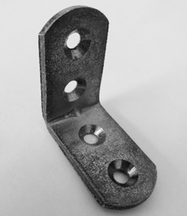
Bends cause slight deformation at the root, which may interfere with adjacent components. Designers should account for this, especially in L-shaped bends. Some CAD tools now include automatic bend compensation features.
Commonly Used Symbols in Sheet Metal Drawings
Chamfering (C)
Chamfers remove sharp edges for safety. The notation “C3” specifies a 3mm chamfer.

Fillets (R)
Rounded edges prevent injuries and improve aesthetics. Notation “R5” indicates a 5mm fillet.

Edge Symbols
These indicate burr treatment requirements. For instance, specifying “-0.05 to -1mm” defines allowable burr removal depth.
Diameter (Ø)
The Ø symbol is used for hole dimensions, such as pilot holes and weight reduction cutouts.

Datums
Reference points for positioning and alignment during fabrication and inspection.

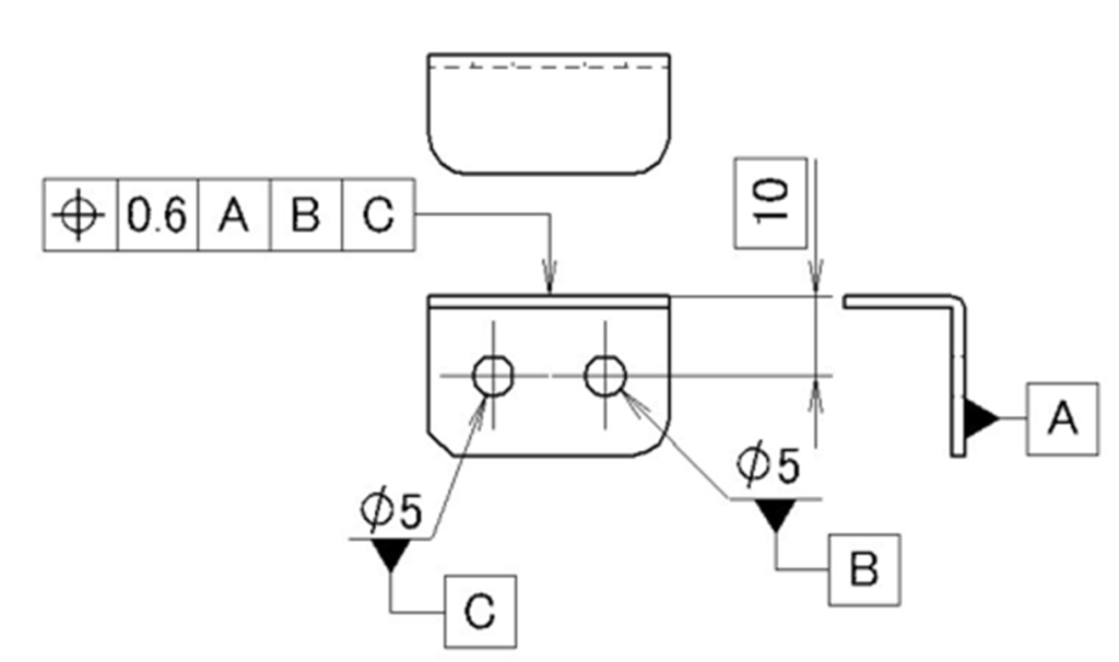
Geometric Tolerances
- Position tolerance: Defines precise hole placement, but is rarely used in sheet metal.
- Perpendicularity tolerance: Indicates bend accuracy, but angle tolerances are more commonly applied instead.
Common Sheet Metal Fabrication Issues & Solutions
Springback in Bending
Springback is a phenomenon in which the sheet metal, which has been pushed into the desired angle by the punch, opens slightly when the punch is released and tries to return to its original position. Measures to prevent this phenomenon include two-stage bending, striking, V-notch, and ribbing (wedge).
Two-stage bending is a method where the material is bent to a certain degree to the desired angle the first time, and then bent again for finishing. Striking is a method where a dent is made at the point of bending, and V-notch is a method where a V-shaped dent is made at the point of bending.
Ribbing (wedge) is a process that adds triangular ribs to the bending part. You can see the ribs in the center of the bent part in the diagram.

Hole Deformation Near Bends
Holes placed too close to bends may distort. To prevent this:
- Maintain a minimum hole-to-bend distance of four times the sheet thickness.
- If spacing is limited, drill holes after bending (though this increases costs).
Bend Interference in Unfolded Models
3D CAD models may appear correct, but interference can arise when unfolded. Always check the unfolded view for interferences.
Insufficient Thread Depth in Thin Sheets
Threads in thin sheets may have inadequate engagement, causing loosening. Solutions include:
- Burring: Raises material around the hole to increase thread depth.
- Using inserts for secure fastening.
Conclusion
Understanding the fundamentals of sheet metal design is crucial for creating manufacturable and cost-effective parts. By following best practices in design, considering fabrication constraints, and proactively addressing common challenges, you can enhance production efficiency, minimise errors, and reduce costs. A well-structured sheet metal design guide ensures smoother collaboration between designers and manufacturers, leading to higher-quality, more reliable components.
For more insights into sheet metal design and manufacturing, explore our other resources or contact us for expert guidance.