BLOG » Design Tips for Automatic Machined Plate Quotations
Design Tips for Automatic Machined Plate Quotations
When modeling components for machining, it’s essential to design with an understanding of how the actual machining process will be carried out. We have seen already few ways to get significantly cheaper components. After our guide on how to avoid automatic quotation error for sheet metal, this time we’ll discuss the key design tips for automatic machined plate quotations that you need to keep in mind.
Design Tips for Automatic Machined Plate Quotations: Pockets and Radii
The design of pockets and their corresponding corner radii holds immense significance. These elements not only contribute to the overall aesthetics but also play a pivotal role in ensuring optimal functionality and manufacturability of custom machined plates. In this section, we delve into essential design insights, guiding you through the art of crafting pockets that seamlessly balance form and function while addressing the intricacies of corner radii. To help you get an automatic quote for your custom milling component, we’ll explore three different pocket types: closed pocket, open pocket, and stepped pocket.
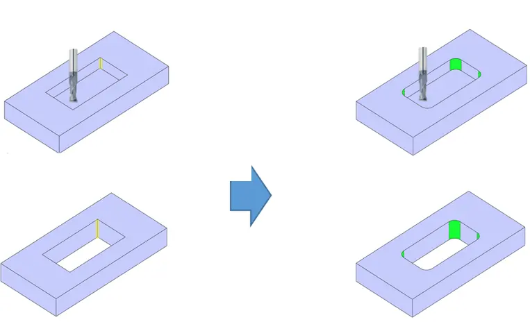
Closed Pocket
For a pocket where all four sides are closed, the movement of the end mill is as shown in the visual below. Therefore, angles smaller than the diameter of the end mill cannot be machined. Thus, it is necessary to provide internal radii at all four corners.
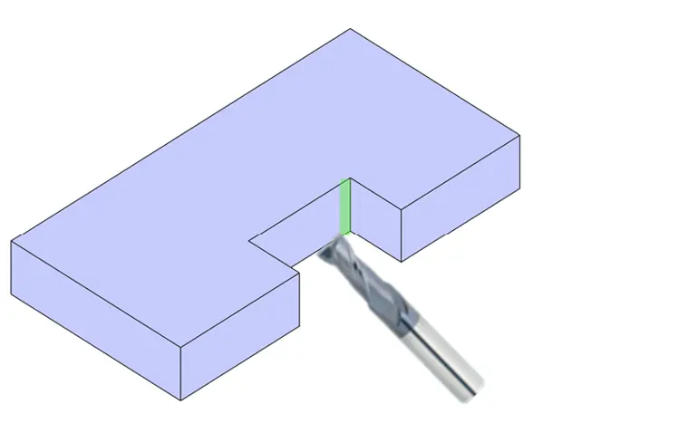
Open Pocket
However, in the case of an open pocket where the surrounding four sides are not enclosed and it is a through-hole shape, it is possible to machine pocket shapes without internal radii by carefully planning the entry direction of the cutting tool.
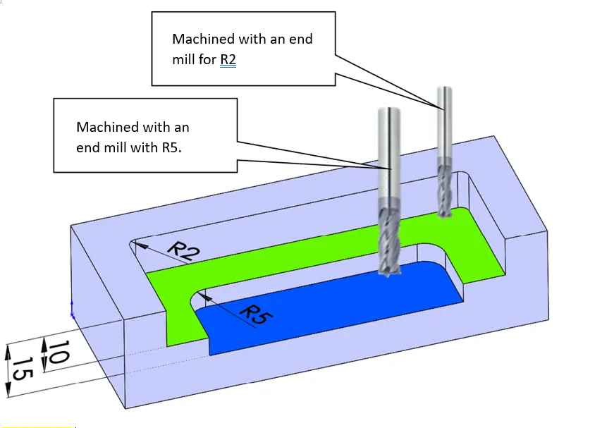
Stepped Pocket
In the case of a stepped pocket like the one shown below, the shallower pocket is specified with a corner radius R2, so it is machined using an end mill designed for R2. On the other hand, the deeper pocket is specified with a corner radius R5 and it will be machined accordingly. As the depth increases, a thicker end mill is required, so careful attention is necessary.
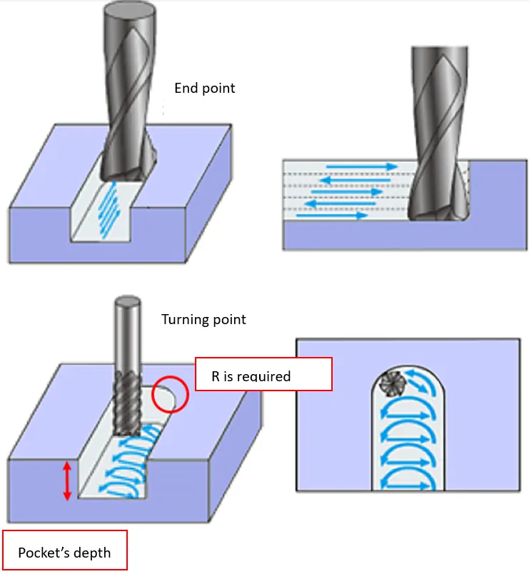
Specifying R at the End and Turnaround Points of the End Mill
At the end and turnaround points of the end mill, an R corresponding to the diameter of the end mill is always required. The image below illustrates the behavior of the end mill at these points. The necessary R value changes depending on the depth of the pocket, in order to machine it with the optimal diameter of the end mill.
Drilling Holes for Surface Treatment
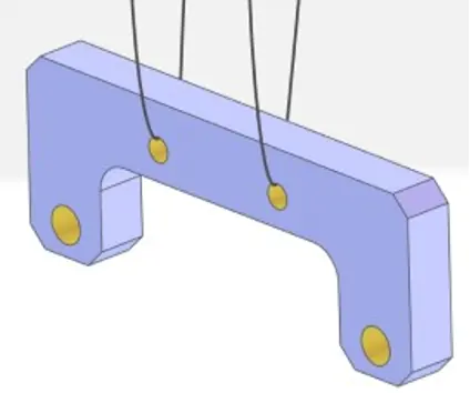
When performing surface treatment on machined parts, it is sometimes necessary to drill holes to suspend the parts during the surface treatment process.
In such cases, there might be spots with inadequate surface treatment on the inside of the holes intended for surface treatment. The image below illustrates the suspension of parts during surface treatment.
Summary
While 3D models offer great freedom in shaping, the actual machining process introduces various constraints due to factors such as the shape and orientation of the cutting tools. Therefore, when designing, it’s important to give significant importance to the pocket area in order to make it actually manufacturable by the end mill.Any constraints will in fact lead to a failure in the automatic quotation process for the custom milling part.This does not apply to only end mill: be sure to pay attention to the characteristics and movements of each tool when designing.