Dopuszczalne tolerancje wymiarowe
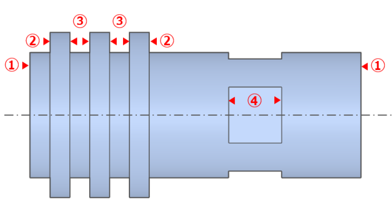
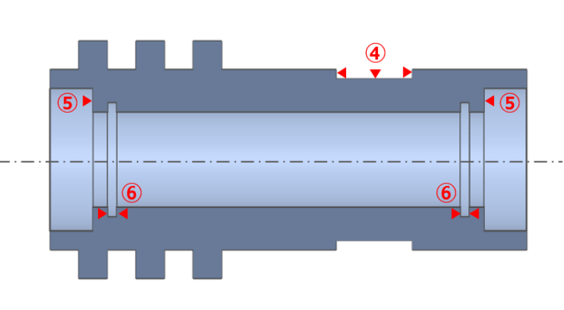
  • Podczas przesyłania danych 3D CAD można określić dowolne tolerancje wymiarowe dla elementów, dla których nie są wyświetlane wymiary ani tolerancje.
  • Minimalny zakres możliwych do zadania tolerancji zależy od kombinacji kształtu elementu.
  • W zależności od innych ustawień dokładność w podanym zakresie może nie być obsługiwana przez usługę.

Tolerancje pasowania

The fit tolerances that can be set for turning machining and secondary machining are as follows.

Type of MachiningFit Tolerances
turningMetal: Grade IT6 or above
Resin::Grade IT7 or above
  • MC
  • (Secondary Machining)
Metal: Grade IT7 or above
Resin::Grade IT7 or above

Uwaga

  • „Poniższe powłoki powierzchniowe nie mogą być określone przy zakresie tolerancji mniejszym niż 0,1.”
  • Surface Treatment|Trivalent Chromated (clear),Trivalent Chromated (black), Salt Bath Nitriding, Hard Anodized (Clear)​

Tolerancje wymiarowe dla całkowitej długości (L) i długości (ℓ)

The following tolerances can be specified for the total length and the length of the individual parts.

[mm]

Metal Full Length (L) and Length (ℓ)
Example of Minimum Tolerance Range
L,ℓ ≦ 200 * ±0.02 0.04
200 <L,ℓ ≦ 500 ±0.05 0.1
500 < L,ℓ ±0.2 0.4
*The range that can be set will change for the following thin plates.
Metal Full Length (L) and Length (ℓ)
Example of Minimum Tolerance Range
L ≦ 5 150<D ±0.1 0.2
L<10 50 ≦ D
Resin​ Full Length (L) and Length (ℓ)​
Example of Minimum Tolerance​ Range​
L,ℓ ≦ 100​ ±0.05 0.1​
100< L,ℓ ≦ 200​ ±0.1​ 0.2
200< L,ℓ ≦ 300 ±0.2 0.4
23564_01_A_deEN
23564_02_A_deEN

[mm]

Resin Full Length (L) and Length (ℓ)
min. Tolerance Range
L,ℓ ≦ 100 ±0.05 0.1
100 < L, ℓ ≦ 200 ±0.1 0.2
200 < L, ℓ ≦ 300 ±0.2 0.4
Resin​ Full Length (L) and Length (ℓ)​
Example of Minimum Tolerance​ Range​
L,ℓ ≦ 100​ ±0.05 0.1​
100< L,ℓ ≦ 200​ ±0.1​ 0.2
200< L,ℓ ≦ 300 ±0.2 0.4
23564_03_A_deEN

Tolerancje średnicy wewnętrznej rowka (d), szerokości rowka (w) oraz wymiarów położenia (ℓ)

Tolerancje, które można ustawić dla średnicy zewnętrznej, są następujące.

[mm]

Tolerances for Groove Outer Diameter (D)​​ Minimum Tolerance Range​
Uniform ±0.02​ 0.04
Groove Width (w) ​ Minimum Tolerance Range​
Uniform ±0.05​ 0.1​
Position Dimensions (ℓ) Minimum Tolerance Range
ℓ≦150 ±0.05 0.1
150<ℓ≦400 ±0.15 0.3
400<ℓ ±0.3 0.6
23564_04_deEN

*Nie można dodać tolerancji pomiędzy powierzchniami średnicy wewnętrznej i zewnętrznej.

Tolerancje średnicy wewnętrznej rowka (d), szerokości rowka (w) oraz wymiarów położenia (ℓ)

Tolerancje, które można ustawić dla średnicy wewnętrznej, są następujące.

[mm]

Tolerances for Groove Inner Diameter (d) Minimum Tolerance Range​
±0.05​ 0.1
Groove Width (w) Minimum Tolerance Range​
±0.07 0.14​
Position Dimensions (ℓ) Minimum Tolerance Range​
±0.1​ 0.2​
23564_05_deEN
  • *Nie można dodać tolerancji pomiędzy rowkiem wewnętrznym a innymi elementami.
  • Wyjątek stanowią wymiary położenia mierzone od czoła elementu ℓ.

Tolerancje dla poszczególnych elementów

Tolerancje, które można ustawić pomiędzy poszczególnymi elementami geometrycznymi, są następujące.
23564_06_deEN
23564_07_deEN

[mm]

No Shape Element (2) Outer Diameter Side (3) External Groove Side (4) Pocket Surface (5) Inner Diameter Bottom (6) Internal Groove Side
(1) Both End Faces 0.04~ 0.04~ 0.1~ 0.04~ 0.2~
(2) Outer Diameter Side
(3) External Groove Side 0.2~
(4) Pocket Surface 0.04~
(5) Inner Diameter Bottom 0.04~
(6) Internal Groove Side 0.2~
23564_08_A_deEN

[mm]

No Shape Element (5)Precision Hole Centre (6)Straight Hole Centre (7)Tapped Hole Centre (8)Insert Hole Centre (9)Countersunk Hole Centre (10)Slotted Hole/Keyway
(1) Both End Faces/Central Axis 0.1~ 0.2~ 0.2~ 0.2~ 0.2~ 0.2~
(2) Outer Diameter Side
(3)
External Groove Side
0.2~
(4)
Pocket Surface
0.04~
(5)
Precision Hole Centre
(6)
Straight Hole Centre
(7)
Tapped Hole Centre
(8)
Insert Hole Centre
(9)
Countersunk Hole Centre
(10)
Slotted Hole/Keyway

Wskazówka

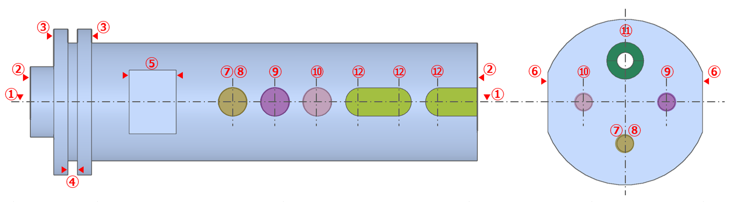
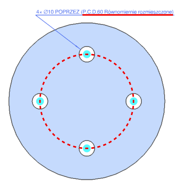
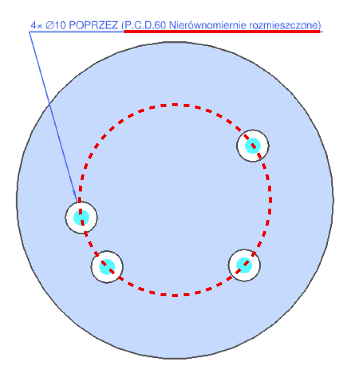
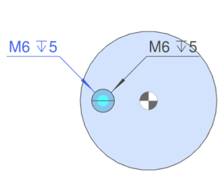
    • (1) Otwory na tym samym okręgu nazywane są P.C.D. (średnica podziałowa). Otwory krzyżowe nie są obsługiwane.
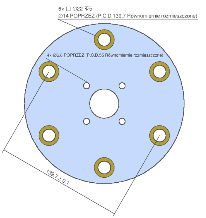
    • (2) P.C.D is recognized even with different hole types.
    • (3) P.C.D. is recognised regardless of whether the positions of the holes are equally or unequally divided. ​
    • (4) It is possible to add diagonal dimensions that indicate the distance between the holes and the P.C.D.
P.C.D. Equally divided P.C.D. Unequally divided The distance between P.C.D. holes.

Uwaga

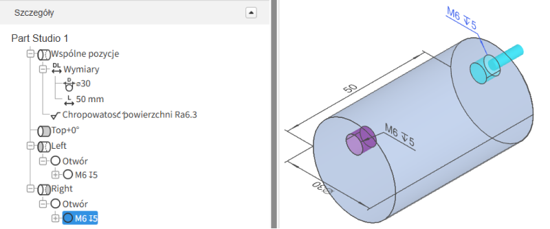
  • Rozpoznawanie P.C.D. w systemie meviy dla części toczonych ma charakter dodatkowy i referencyjny.
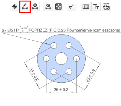
  • If you need to specify the tolerance between holes, please select the “Add tolerance” icon and specify the tolerance for the target position.

Wskazówka

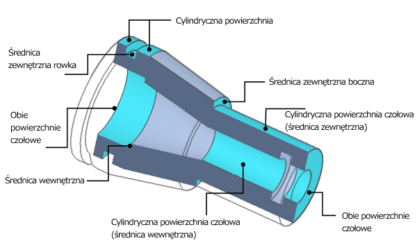
  • The positional relationship of holes on both end faces of the reference model in the figure below is a general tolerance.

Uwagi

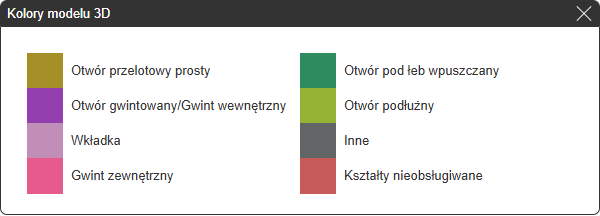
  • 3D Model Color Schemes
  • If a colour scheme for an unsupported shape is displayed, automatic quotation is not available.

Tolerancje geometryczne

Możliwe warunki ustawienia tolerancji geometrycznych są następujące.
configurable plane
  • Nie można określać tolerancji dla otworów, wpustów (średnica wewnętrzna/zewnętrzna), wycięć (w tym kieszeni), rowków wewnętrznych oraz rowków czołowych.
  • Jeśli dla gwintowanego elementu określono bazę lub tolerancję geometryczną, gwarantujemy ją na podstawie wartości zmierzonej przed wykonaniem gwintu.
Configurable geometric tolerances
*Depending on the material and size, the estimate may be provided by the person in charge.
Geometric Tolerance Type Symbol Plane Cylindrical surface Datum Datum target area Tolerance value
Płaskość surface 0.01~0.1
Równoległość necessary surface 0.01~0.1
Prostopadłość necessary surface 0.01~0.1
Okrągłość surface 0.01~0.1
Współosiowość necessary axis line 0.01~0.1
Prostoliniowość surface 0.01~0.1
Walczystość surface 0.01~0.1
Circular rount necessary axis line 0.01~0.1
Bicie całkowite necessary axis line 0.01~0.1
Tabela zgodności (materiały, obróbka powierzchniowa, obróbka cieplna)
Compatibility table (surface treatment)
  • *Tworzywo sztuczne zgodne z [Normami dokładności tolerancji geometrycznych dla obróbki tokarskiej] >>> Standardowa tolerancja wymiarowa dla obróbki bez wskazań
  • *Chrom twardy (cienka warstwa) i isonit mogą być szlifowane po obróbce powierzchniowej w zależności od wymaganej dokładności, w takim przypadku powłoka może nie pozostać na obrabianej powierzchni.

Ostatnio przeglądane artykuły