- HELP
- How to use
- Quotation conditions settings
- [CNC Turning] Quotation Settings
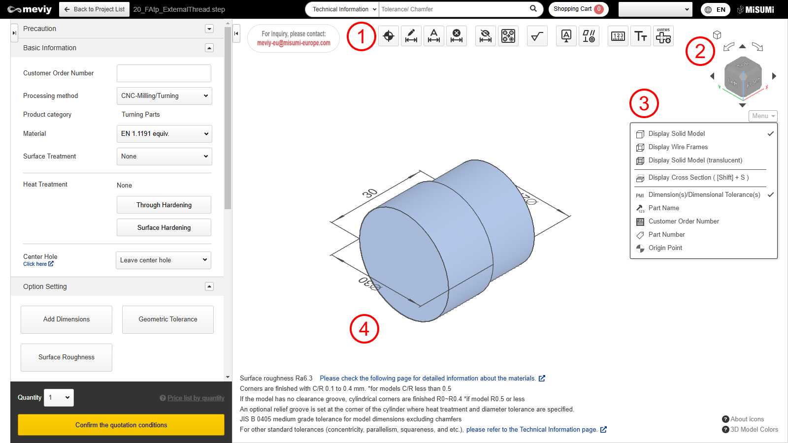
- How to Use the 3D Viewer
How to Use the 3D Viewer

| Function Name | What You Can Do |
|---|---|
|
Move the design’s origin point. → Change a Design’s Origin |
|
Add dimensions and dimensional tolerances. → Add/Remove Dimensions and Dimensional Tolerances |
|
Batch add coordinate dimensions based on the origin point. → Add/Remove Dimensions and Dimensional Tolerances*This function is not available when a precision hole is set as the origin. |
|
Remove added dimensions. → Add/Remove Dimensions and Dimensional Tolerances |
|
Hides dimensional tolerances guaranteed by “Default General Tolerance Standards for Machined Dimensions.” |
|
You can split holes grouped during shape recognition. → Splitting Grouped Holes |
| Function Name | What You Can Do |
|---|---|
|
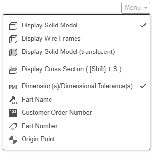
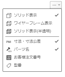
You can change the font size of the PMI display. → Changing Font Sizes |
|
Download image files that capture each orthogonal direction of the 3D models and arrange them via 3rd angle projection. |
|
This function allows measurement of models uploaded.→Measuring 3D models |

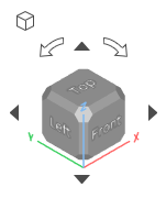
Rotate the cube to change the orientation of the currently displayed parts.
Click  [Isometric View] to return to the isometric view (default orientation).