- HELP
- How to use
- Quotation conditions settings
- [CNC Turning] Quotation Settings
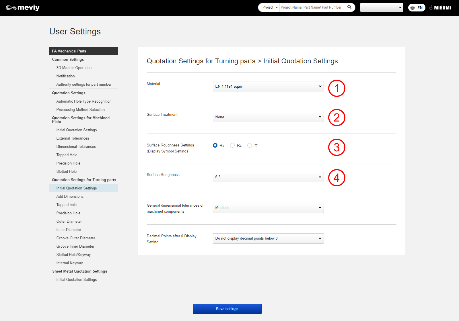
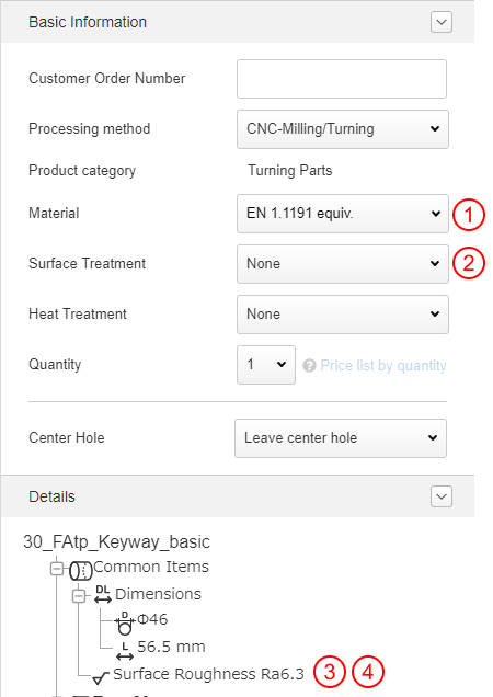
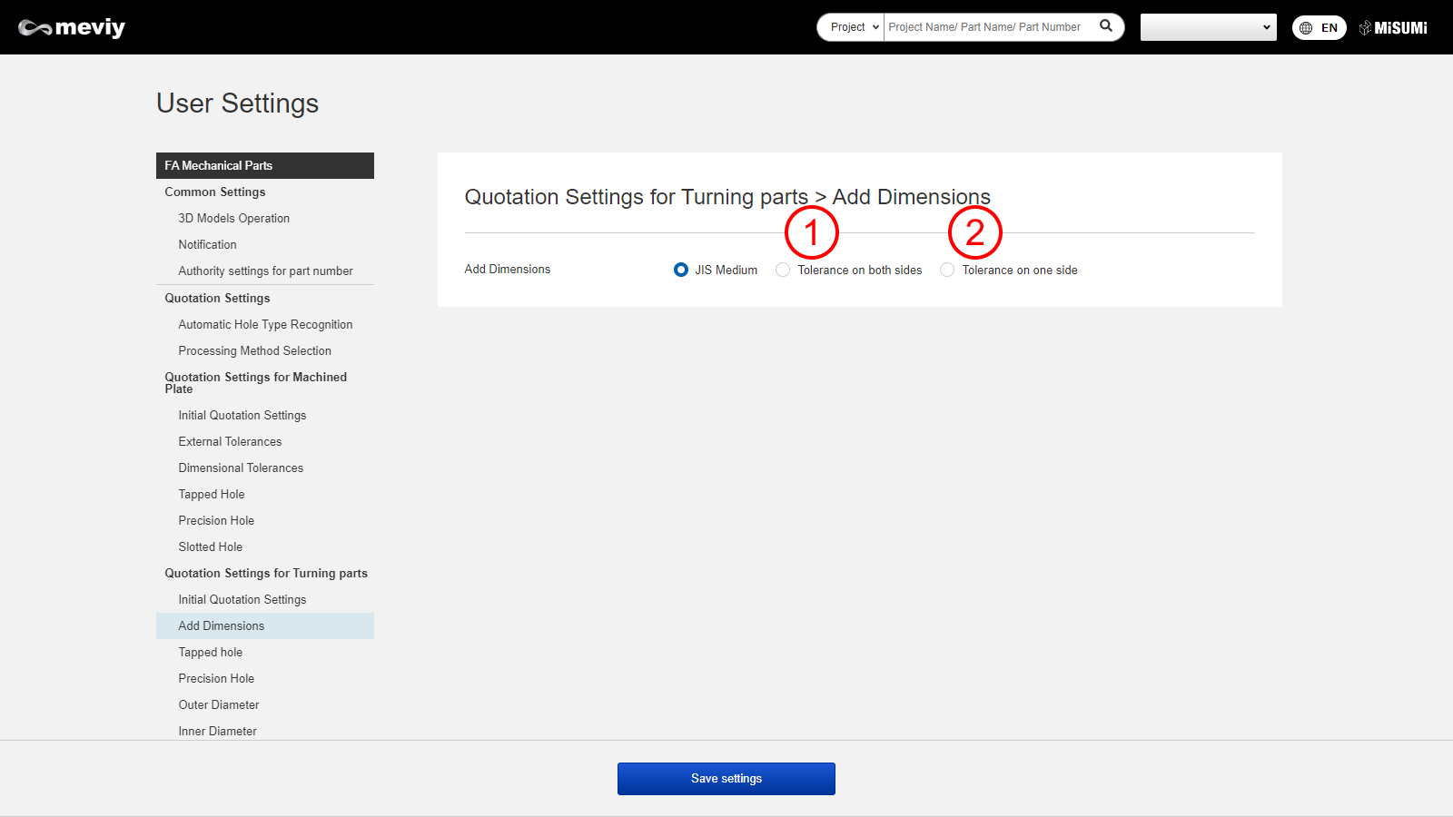
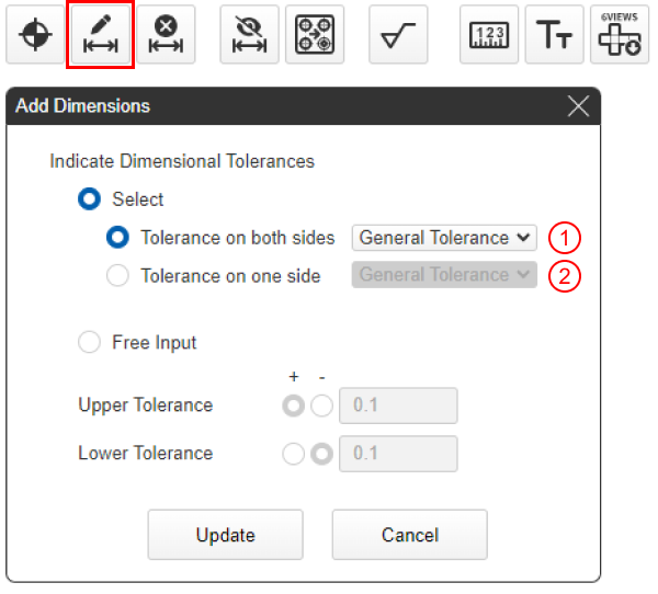
- User Settings (Turning Parts)
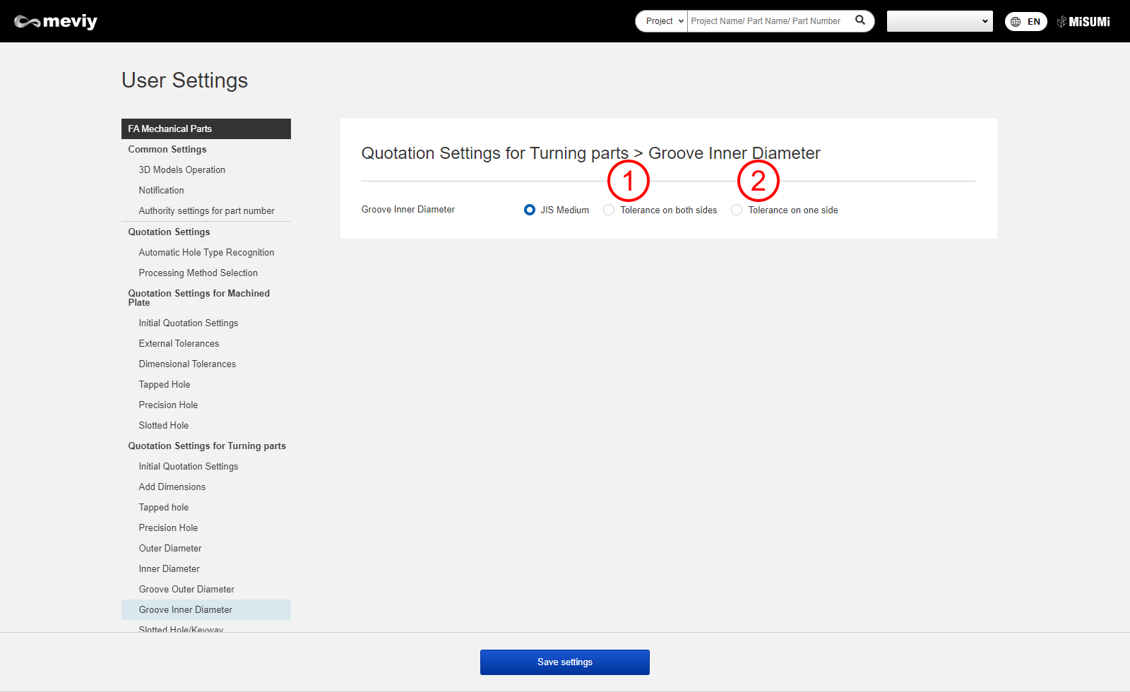
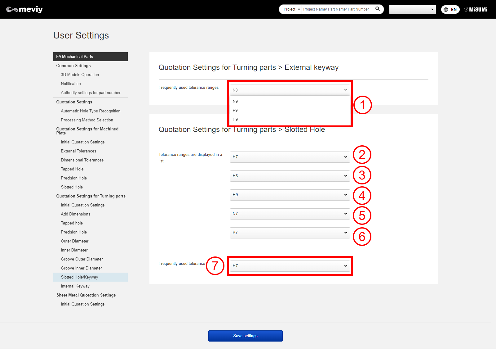
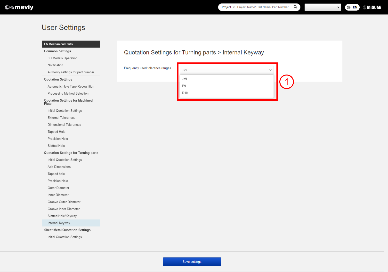
User Settings (Turning Parts)

Tip
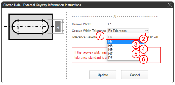
If the groove width matches JIS standards (B 1301:1996), this is recognized as a keyway.
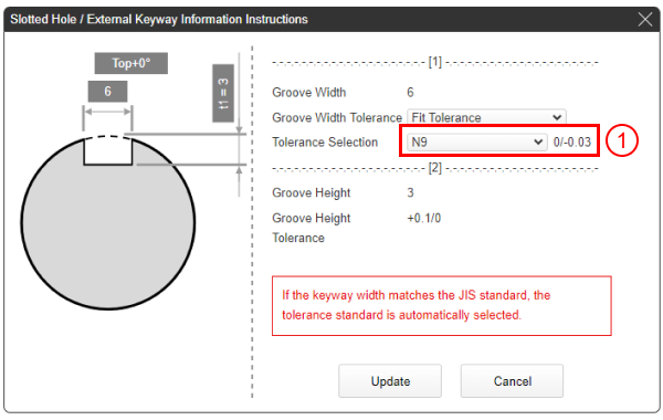
If the groove width does not match JIS standards (B 1301:1996), this is recognized as a slotted hole.
See here for the keyway standards table
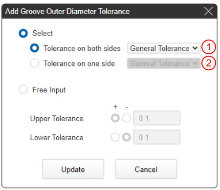
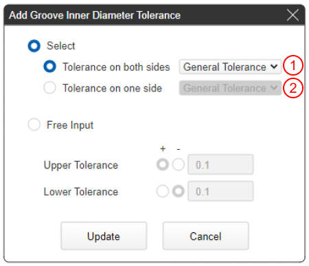
Tip
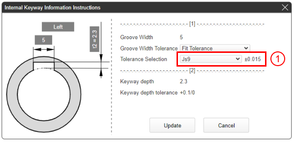
If the groove width matches JIS standards (B 1301:1996), this is recognized as a keyway.
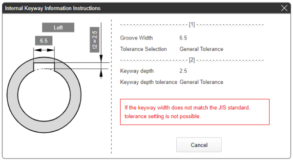
If the groove width does not match JIS standards (B 1301:1996), this is handled as “General tolerance” and tolerance cannot be selected.
See here for the keyway standards table