- HELP
- Technical Information
- CNC Turning
- Design Guidelines
- Rules for Dimension Notation on 3D Viewer
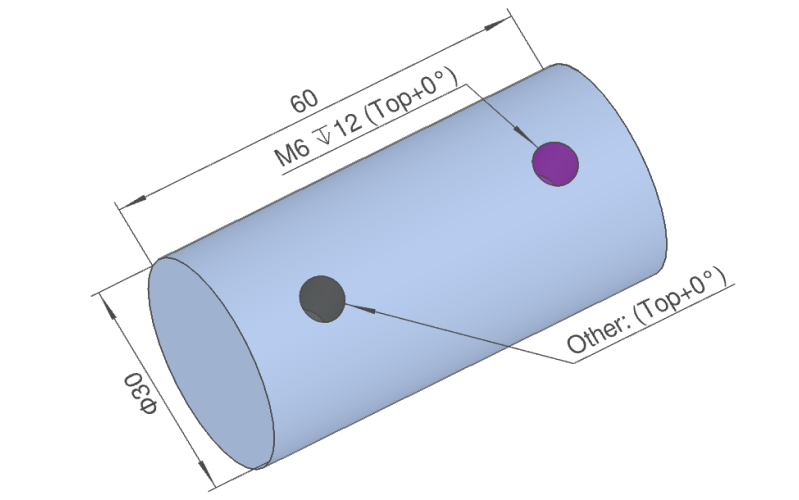
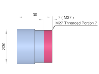
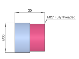
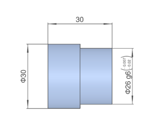
Rules for Dimension Notation on 3D Viewer
| Settings | Non-precision | ||||
|---|---|---|---|---|---|
| Thread Length Settings | |||||
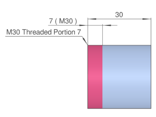
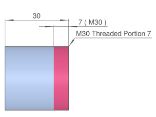
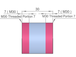
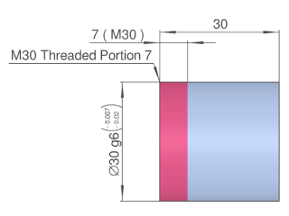
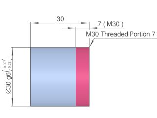
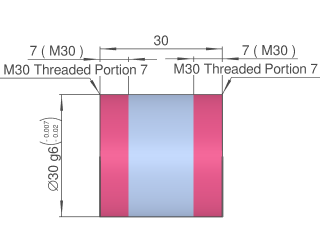
| Specified length on left side | Specified length on right side | Specified length on both sides | Fully threaded | ||
| Image |  |
 |
 |
 |
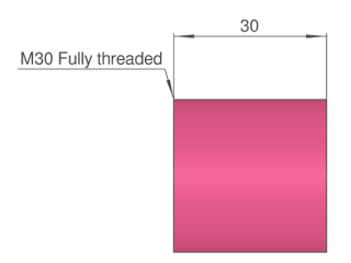 |
| Set Value | ø30 | ||||
| M30 thread length min.7mm|7(M30) | | M30 thread length min.7mm|7(M30) | |||
| M30 thread length min.7mm|7(M30) | M30 thread length min.7mm|7(M30) | M30 Fully threaded | |||
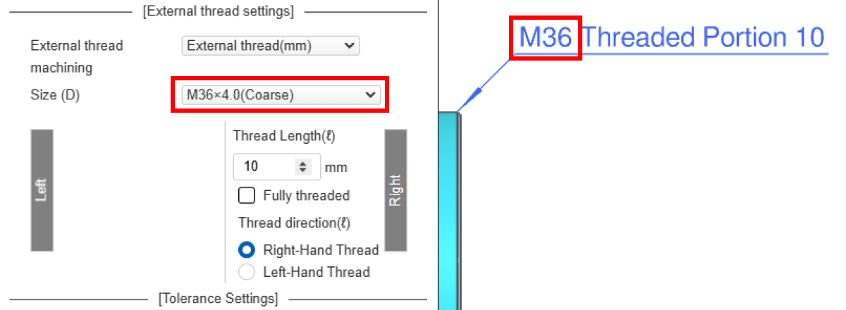
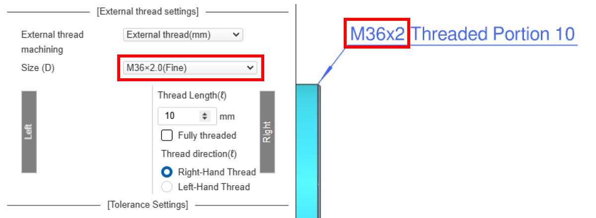
Tip
When setting the thread in meviy, fine thread is displayed for the pitch, but coarse thread is not displayed.
 |  |
| Settings | Non-precision | ||||
|---|---|---|---|---|---|
| Thread Length Settings | |||||
| Specified length on left side | Specified length on right side | Specified length on both sides | Fully threaded | ||
| Image | 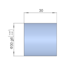 |
 |
 |
 |
|
| Set Value | ø30 g6 (-0.007/-0.02) | ø30 g6 (-0.007/-0.02) | ø30 g6 (-0.007/-0.02) | ø30 g6 (-0.007/-0.02) | |
| M30 thread length min.7mm|7(M30) | M30 thread length min.7mm|7(M30) | M30 thread length 7mm|7(M30) | |||
| M30 thread length 7mm|7(M30) | |||||
| Settings | Non-precision | Precision | |||
|---|---|---|---|---|---|
| Thread Length Settings | Thread Length Settings | ||||
| Specified length | Fully threaded | Specified length | |||
| Image | 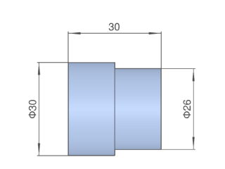 |
 |
 |
 |
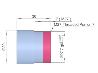 |
| Set Value | ø26 | ø26 g6 (-0.007/-0.02) | ø26 g6 (-0.007/-0.02) | ||
| M27 Thread Length 7|7(M27) | M27 Fully threaded | M27 Thread Length 7|7(M27) | |||
| Settings | Non-precision | Tapered pipe thread settings | |
|---|---|---|---|
| ISO Standard | Specified length | ||
| Image | 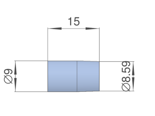 | 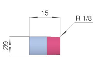 | 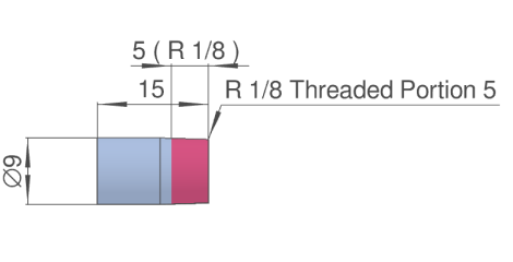 |
| Set Value | ⌀8.89 | R 1/8 | R 1/8 Thread Length 5 |
| Settings | Non-precision | Precision |
|---|---|---|
| Image | 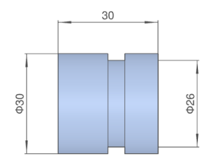 |
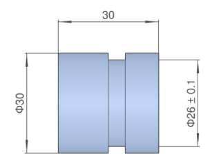 |
| Set Value | ø26 | ø26 ±0.1 |
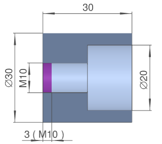
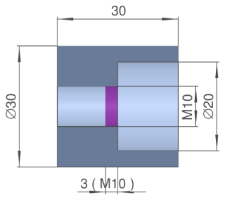
| Settings | Non-precision | ||||
|---|---|---|---|---|---|
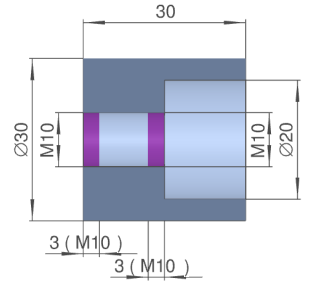
| Internal Thread Settings | |||||
| Specified effective depth on left side | Specified effective depth on right side | Specified effective depth on both sides | Fully threaded | ||
| Image | 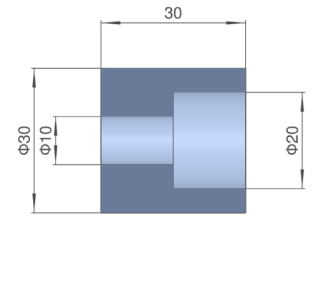 |
 |
 |
 |
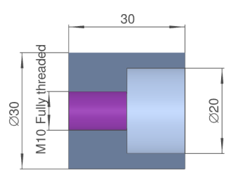 |
| Set Value | ø10 | M10 | M10 | M10/M10 | M10 Fully threaded |
| 3(M10) | 3(M10) | 3(M10)/3(M10) | |||
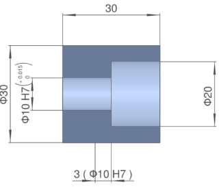
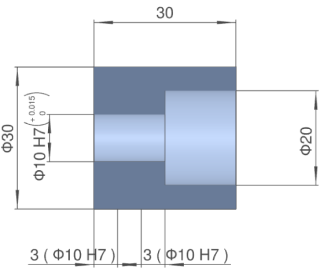
| Settings | Precision | |||
|---|---|---|---|---|
| Specified effective depth on left side | Specified effective depth on right side | Specified effective depth on both sides | Full length | |
| Image | 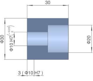 |
 |
 |
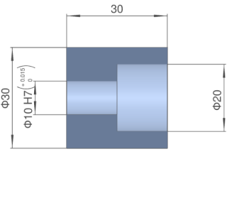 |
| Set Value | ø10H7(+0.015/0) | ø10H7(+0.015/0) | ø10H7(+0.015/0) | ø10H7(+0.015/0) |
| 3(ø10H7) | 3(ø10H7) | 3(ø10H7)/3(ø10H7) | ||
| Settings | Non-precision | Tapered pipe thread settings | |
|---|---|---|---|
| ISO Standard | Specified length | ||
| Image | 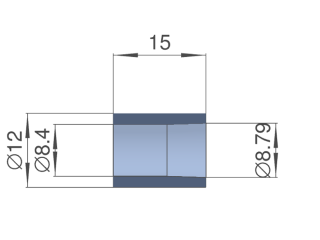 | 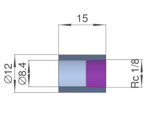 | 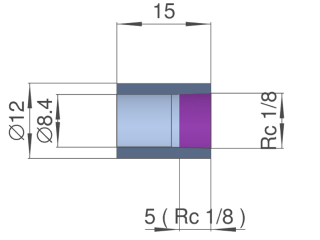 |
| Set Value | ⌀8.89 | R 1/8 | R 1/8 Thread Length 5 |
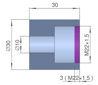
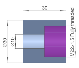
| Settings | Non-precision | Precision | |||
|---|---|---|---|---|---|
| Internal Thread Settings | |||||
| Specified depth | Fully threaded | Specified depth | Full length | ||
| Image | 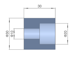 |
 |
 |
 |
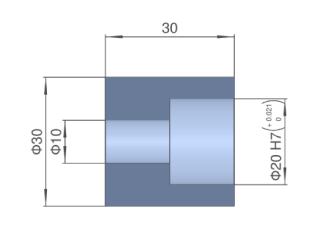 |
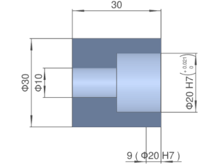
| Set Value | ø20 | M22x1.5 | M22 × 1.5 Fully threaded | ø20 H7 (+0.0021/0) | ø20 H7 (+0.0021/0) |
| 3(M22x1.5) | 9(ø20 H7) | ||||
| Settings | Non-precision | Precision |
|---|---|---|
| Image | 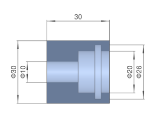 |
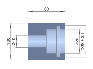 |
| Set Value | ø26 | ø26 ±0.1 |
| Surface roughness | Ra1.6 | Ra3.2 | Ra6.3 |
|---|---|---|---|
| Image |  |
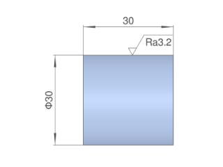 |
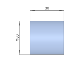 |
| Set Value | Ra1.6 | Ra3.2 | A reference surface roughness value is not displayed |
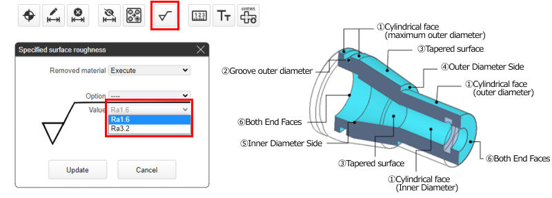
Tip
- The surface roughness value can be specified. See (1) to (6) in the figure to the right for surfaces for which values can be set.
Tip
| Blind/Through | Blind | Through | ||
|---|---|---|---|---|
| Settings | None | Torelance H7, Effective depth 13 | None | Torelance H7, Effective depth 15 |
| Image | 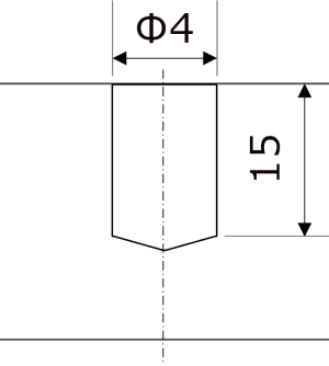 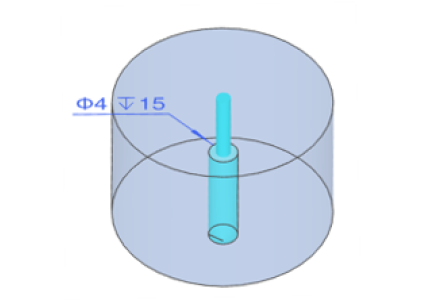 | 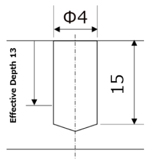 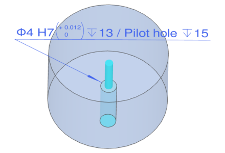 | 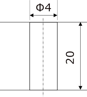 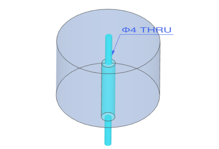 | 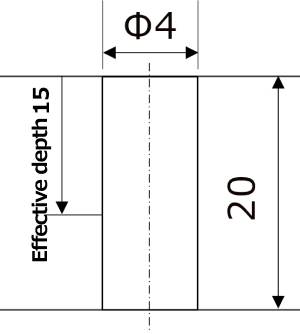 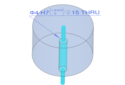 |
| 3D Viewer display | ø4 ↧15 | ø4H7(+0.012/0) ↧13/Pilot hole ↧15 | ø4 THRU | ø4H7(+0.012/0) ↧15 THRU |
| Blind/Through | Blind | Through | ||
|---|---|---|---|---|
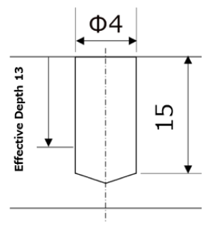
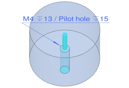
| Settings | Coarse thread | Fine thread: Effective depth 13 | Coarse thread | Fine thread: Effective depth 10 |
| Image |  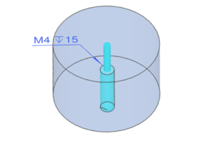 |
  |
  |
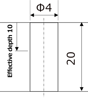 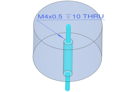 |
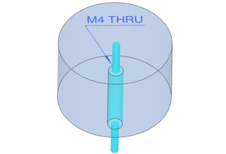
| 3D Viewer display | M4 ↧15 | M4x0.5 ↧13/Pilot hole ↧15 | M4 THRU | M4x0.5 ↧10 THRU |
| Blind/Through | Blind | Through |
|---|---|---|
| Settings | Nominal length 1D | Nominal length 1D |
| Image | 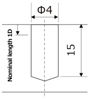 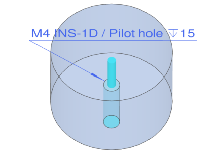 |
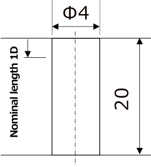 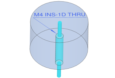 |
| 3D Viewer display | M4 INS-1D/Pilot hole ↧15 | M4 INS-1D THRU |
| Blind/Through | Blind | Through |
|---|---|---|
| Settings | None | None |
| Image | 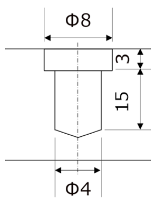 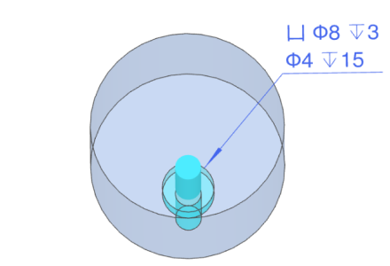 | 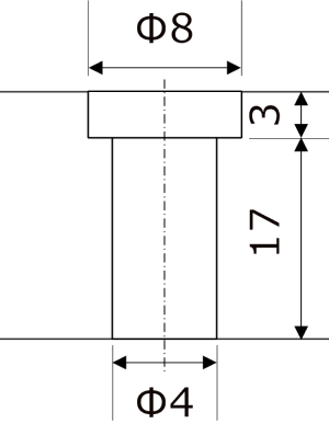 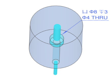 |
| 3D Viewer display | 凵 ø8 ↧3 | 凵 ø8 ↧3 |
| ø4 ↧15 | ø4 THRU |
| Blind/Through | Through |
|---|---|
| Settings | None |
| Image | 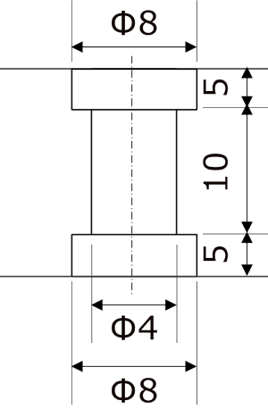 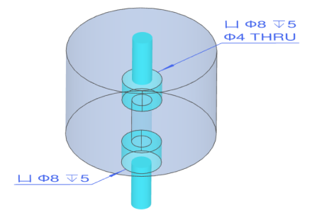 |
| 3D Viewer display | 凵ø8↧5 |
| ø4 THRU | |
| (Opposite side)凵ø8↧5 |
| Blind/Through | Through |
|---|---|
| Settings | None |
| Image | 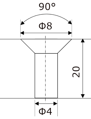 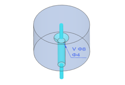 |
| 3D Viewer display | V ø8 |
| ø4 |
Notes
- A hole located on the central axis is recognised as a “hole” supported for automatic quotation
- Please check here for details on recognition conditions. → [FA Mechanical Parts] Turning Parts>Turning Parts Recognition Conditions