- HELP
- Technical Information
- [FA Mechanical Parts] Sheet Metal Parts
- Design Guidelines
- Sheet Metal Quoting Error Troubleshooting
Sheet Metal Quoting Error Troubleshooting
- When uploading a model to meviy, a “Quotation failure” error may occur.
- Below is an overview of why these errors occur and how to resolve them,as well as some example errors.
What is a quotation failure?
Case 1: Failure to read uploaded file
Case 2: Unsupported shape
Case 3: Plate thickness not available
Case 4: Uneven plate thickness
Case 5: Distance between features
Case 6: Bend-to-hole distance
Case 7: Undersized bend height
Case 8: Interference during bending
Case 9: Unrecognized holeshape
What is a quotation failure?
When uploading a model to meviy, an error may occur where the model cannot be auto-quoted.
How to check for errors in the project list
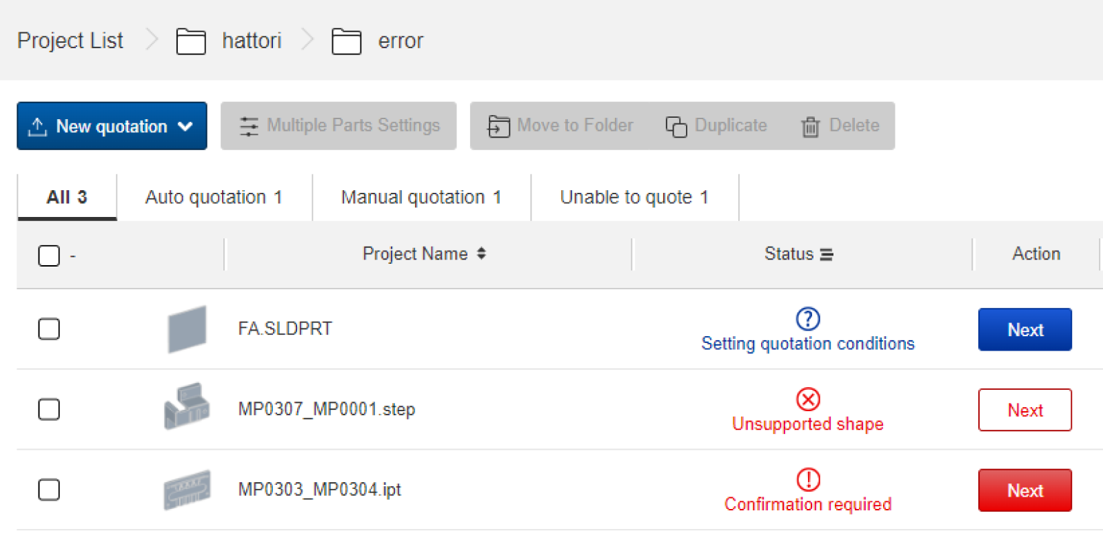
- After uploading a model to meviy, the “” or “” icon will appear if the model cannot be auto-quoted.
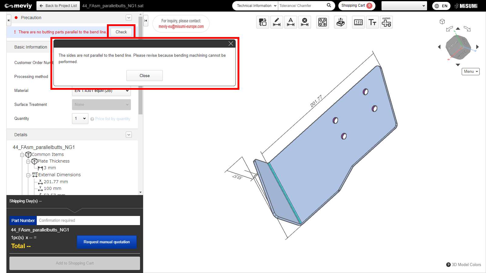
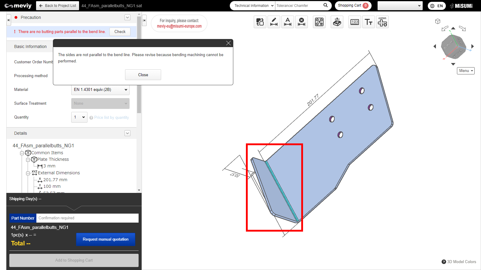
- In this case, please go to the 3D Viewer and confirm the details of the error from the Precaution column.
How to check error messages in the 3D Viewer
- Please open 3D viewer and check “Precaution”.
- If you click “Check”, you will see error messages and a range for auto-quotation.
- Depending on error cause, a range for auto-auotation may not be displayed.
How to locate an error
- Clicking the “Confirm” button will highlight the error location in the model.
- Once this error is resolved, automatic quoting will be possible.
Case 1: Failure to read uploaded file
- This error occurs when a 3DCAD format or extension that is not supported by meviy is uploaded.
- To resolve this, please check the formats supported by meviy and re-upload a supported format.
Notes
- Please see below for the formats and extensions that can be uploaded to meviy.
- Before You Begin>Uploadable CAD File Formats
Case 2: Unsupported shape
- This error is caused by uploading a shape that is not eligible for automatic quotation with meviy’s Sheet Metal Plate service.
- To resolve this, please check the quotable shapes and modify the model accordingly.
Tip
- If the following message is displayed in the 3D Viewer, it corresponds to this error.
- – “There is an unsupported shape.”
Notes
- See below for shapes supported by the Sheet Metal service.
- → [FA Mechanical Parts] Sheet Metal Parts>Applicable parts/Materials>Shapes Eligible for Quotation
Case 3: Plate thickness not available
- This error occurs when the requested plate thickness is not supported.
- To resolve this, modify the model to match the corresponding plate thicknesses.
Tip
- If the following message is displayed in the 3D Viewer, it corresponds to this error.
- – “There are no supported sheet thicknesses.”
Notes
- The part thickness must match one of the gauge thicknesses supported by meviy Sheet Metal.
- Please refer to the following for available sheet thicknesses.
- → [FA Mechanical Parts] Sheet Metal Parts>Applicable parts/Materials>Material, Surface Treatment, Size
Case 4: Uneven plate thickness
- This error occurs when the plate thickness is not constant during modeling or when the R length setting is not within the correct range.
- To resolve this, modify the model to create a uniform sheet thickness.
Tip
- If the following message is displayed in the 3D viewer, it corresponds to this error.
- – “Model sheet thickness is non-uniform.”
Notes
- Please see below for sheet metal modeling guidelines.
- → [FA Mechanical Parts] Sheet Metal Parts>Design Guidelines>Basic Modeling Rules
Case 5: Distance between features
- This error occurs when the distance between holes and end faces, or between holes is below the limit.
- To resolve this, please increase the distance between the hole and the end face/hole.
Tip
- If the following message is displayed in the 3D Viewer, it corresponds to this error.
- – “XX and XX are too close.”
Notes
- See below for minimum distances between holes and end faces/holes.
- → [FA Mechanical Parts] Sheet Metal Parts>Design Guidelines>Range of Machining Limits
- Please also use the measurement function to check the distance.
- → [FA Sheet Metal] Quotation Settings>Measuring 3D models
- If you have any questions, please request a manual quotation by meviy support. See below for assistance on manual quotations.
- →Quotation conditions settings>[FA Sheet Metal] Quotation Settings>Information about manual quotation
Case 6: Bend-to-hole distance
- This error occurs when the bend-to-hole distance is below the limit.
- To resolve this, either increase the distance between the bend and the hole or create an opening on the bend line (clearance hole).
Tip
- If the following message is displayed in the 3D Viewer, it corresponds to this error.
- – “XX and XX are too close.”
Notes
- See below for the required minimum distance between a hole and a bend.
- → [FA Mechanical Parts] Sheet Metal Parts>Design Guidelines>Range of Machining Limits
- See below for rules on openings on the bend line.
- → [FA Mechanical Parts] Sheet Metal Parts>Design Guidelines>Range of Machining Limits
- If you have any questions, please request a manual quotation by meviy support. See below for assistance on manual quotations.
- →Quotation conditions settings>[FA Sheet Metal] Quotation Settings>Information about manual quotation
Case 7: Undersized bend height
- This error occurs when the bending height is below the limit.
- To resolve this, increase the bending height to a sufficient height.
Tip
- If the following message is displayed in the 3D Viewer, it corresponds to this error.
- – “The bend height is too small.”
Notes
- See below for minimum bending heights.
- → [FA Mechanical Parts] Sheet Metal Parts>Design Guidelines>Range of Machining Limits
Case 8: Interference during bending
- This error occurs when the part geometry causes interference during bending.
- To resolve this, modify the part design to avoid interference.
Tip
- If the following message is displayed in the 3D Viewer, it corresponds to this error.
- – “The part and mold are interfering during bending.”
Notes
- See below for guidelines on die interference during bending.
- → [FA Mechanical Parts] Sheet Metal Parts>Design Guidelines>Bending Conditions
Case 9: Unrecognized holeshape
- This error occurs when there is an unrecognized hole shape.
- To resolve this, please change the hole to a supported shape and re-upload the file.
Tip
- If the following message is displayed in the 3D Viewer, it corresponds to this error.
- – “There is an unsupported hole shape.”
Notes
- See below for tapped hole recognition.
- → [FA Mechanical Parts] Sheet Metal Parts>Design Guidelines>Tapped Hole Identification and Selectable Sizes
- → [FA Mechanical Parts] Sheet Metal Parts>Design Guidelines>Friction Drilled/Tapped Holes Modeling and Sizes