- HELP
- Technical Information
- CNC Turning
- Design Guidelines
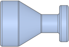
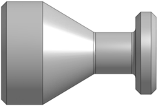
- Difference in Shapes Between the 3D Model and the Finished Product
Difference in Shapes Between the 3D Model and the Finished Product

Notes
-
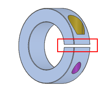
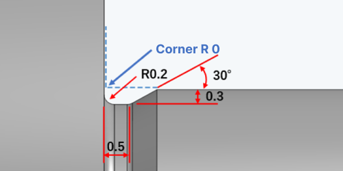
- A standard retaining ring grooving tool has corner R0.2
- For retaining ring standards, click here.>>>Specifications for External Thread and Internal Thread, Keyways, Holes and Pockets
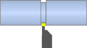
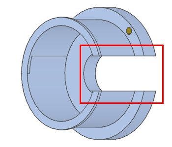
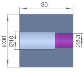
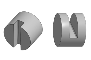
Outer diameter grooving

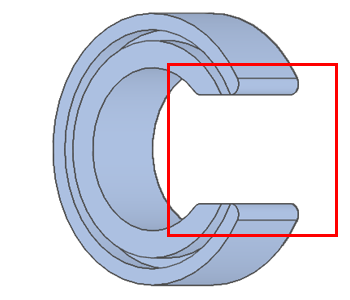
Inner diameter grooving

Caution
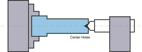
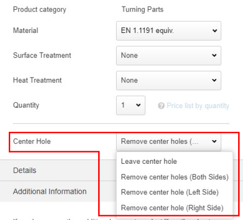
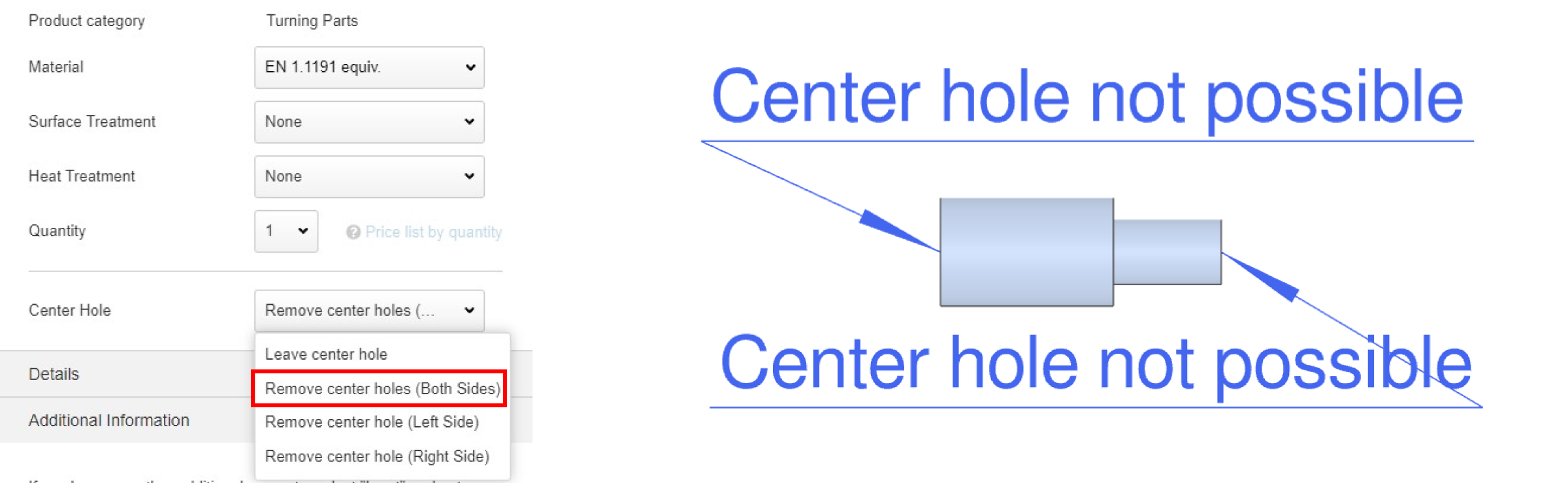
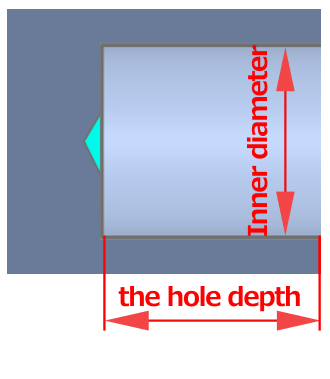
- 「”Center hole cannot be left” can be selected, but there may be restrictions on the shapes that can be machined that make the option unavailable. When this occurs, check the “Precaution” in the upper-left corner of the 3D Viewer.
Notes
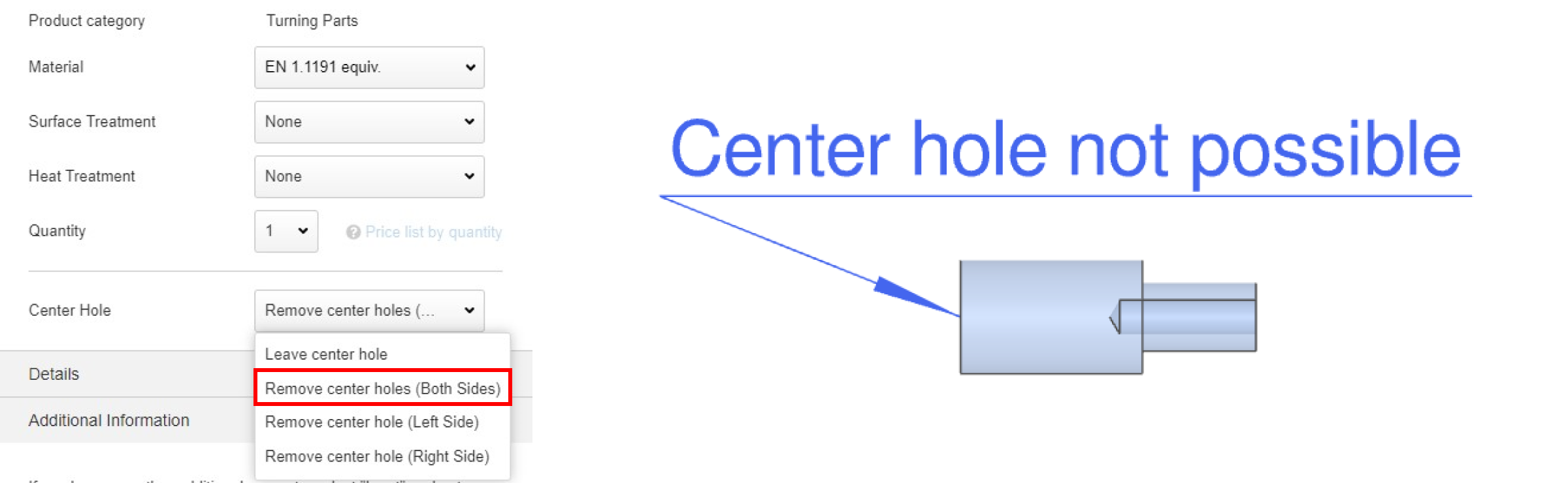
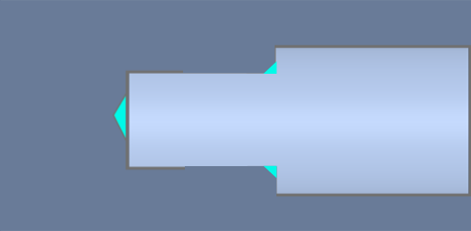
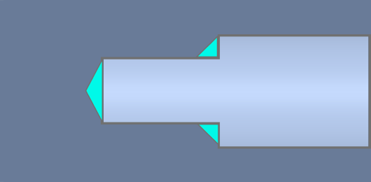
(1) If you select “Remove center hole”, an arrow will point to the part.
(2) If the component has an inner diameter, no arrow will point to the part.
| Shape patterns | Inner diameter hole does not have a step | Inner diameter hole has a step |
|---|---|---|
| A |  |
 |
| Drill tip shape remains (flat bottom will be 1mm or more) | ||
| B | 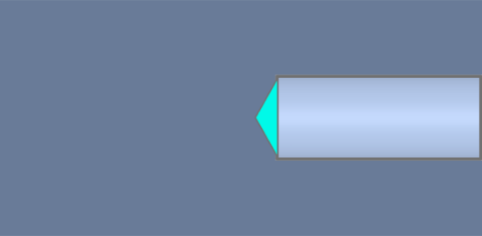 |
 |
| Drill tip shape remains, no flat bottom | ||
Tip
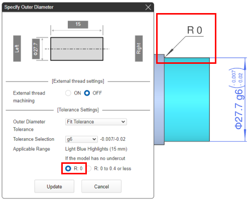
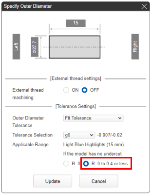
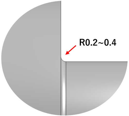
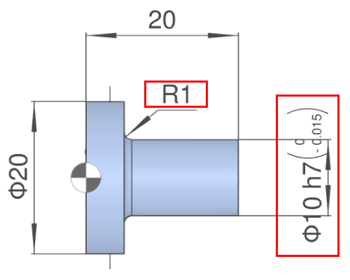
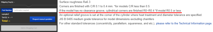
Corner R0 has a width of less than corner R0.2 to R0.4, so the depth may be less than 0.5mm. You cannot choose.① When machining with R0.4 tools
②When machining with R0.2 tools with R0.4 tools
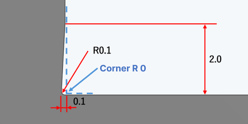
③ If the length of the shaft is short, it may be machined with a tool with a 0.1mm radius on the end face that contacts the shaft.
Notes
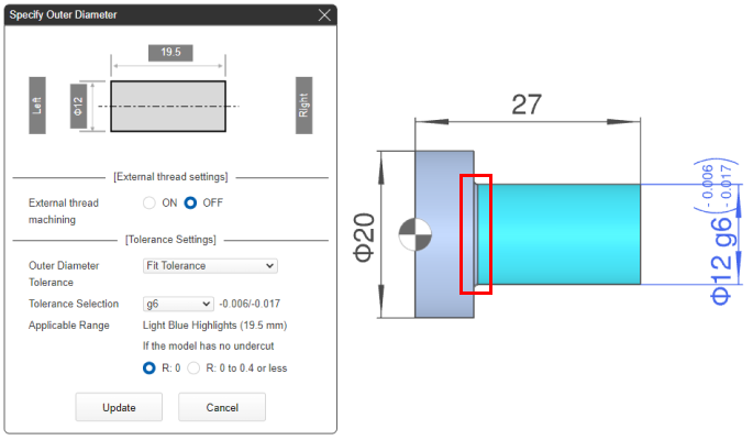
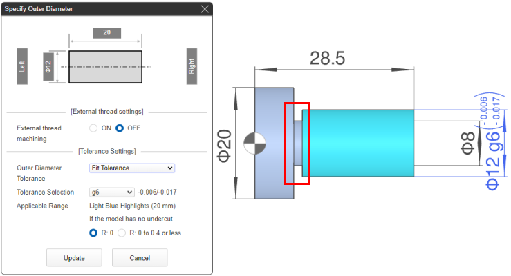
In the following cases, “Corner R0” does not apply.
| (1) The model has corner R0.5 or greater | (2) The model has a relief groove |
 |
 |
Tip
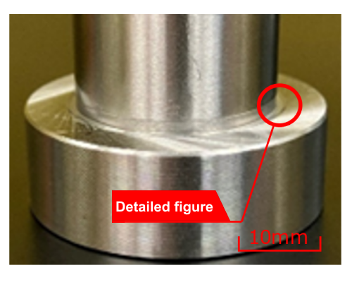
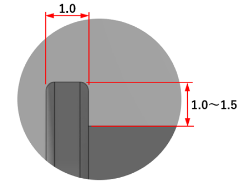
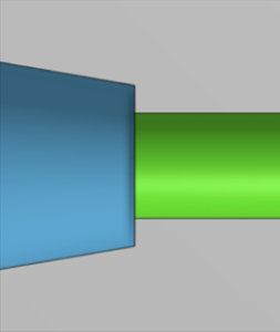
- Arbitrary R shape of cylindrical corner
- ① Machining R remains
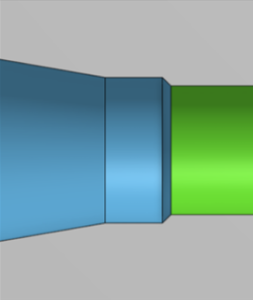
- ② Relief groove (1) Minimum clearance only at the cylindrical corner
-
Finished shape after
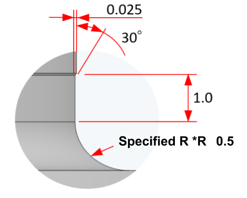
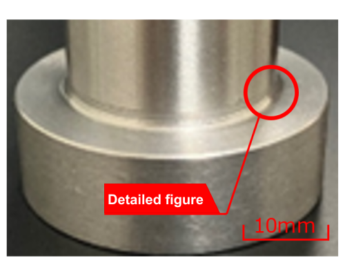
Detailed figure
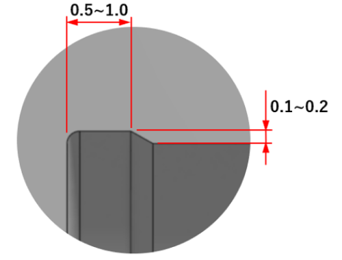
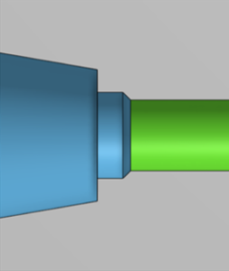
- ③ Relief groove (2) Relief shape on cylindrical part + flange part
-
Finished shape after machining
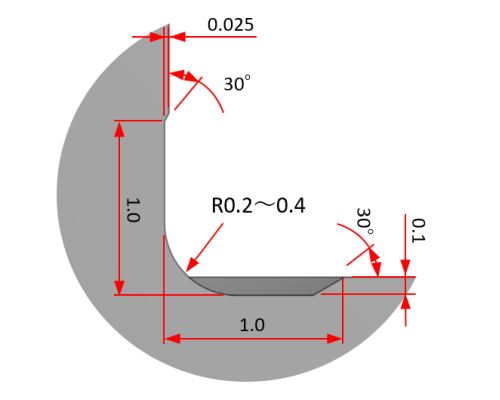
Detailed figure
If the corners are modeled with R0.5 or higher, the shape will be as shown below.
 Modeling of R0.5 or higher in corners
- Finished shape after machining
- Detailed figure
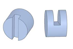
Any relief groove below may be set.
 Cross section
 ①Detailed figure
 ②Detailed figure
Notes
At the bottom left of the 3Dviewer, you can see the handling information for the cylindrical corners.


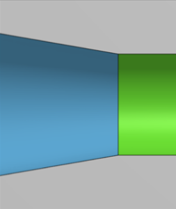
| External Thread | Internal Thread | ||
|---|---|---|---|
| Modelling | Without undercut | 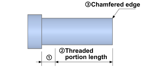 |
 |
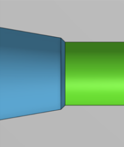
| With undercut | 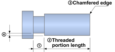 |
 |
|
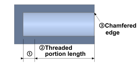
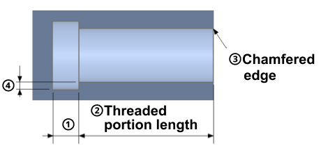
| (1) Lower limit for the length of the incomplete thread and the width of the undercut. | Pitch × 2.0 | Pitch × 2.5 + 2 | |
| (2) Lower limit of the length of the threaded (external thread) and the depth of the threaded (internal thread). | Pitch × 2.0 | Pitch × 2.0 | |
| (3) Chamfered edge | Chamfered to prevent burr | Chamfered to prevent burr | |
| (4) Minimum undercut depth value | Pitch × 0.75 | Pitch × 0.75 | |
Caution
Parts with “Pitch × 0.75” or less set to the minimum value for the undercut depth(4) can be machined, but thread marks may occur.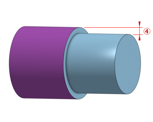 Reference model
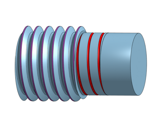 Actual finished shape after machining
Tip
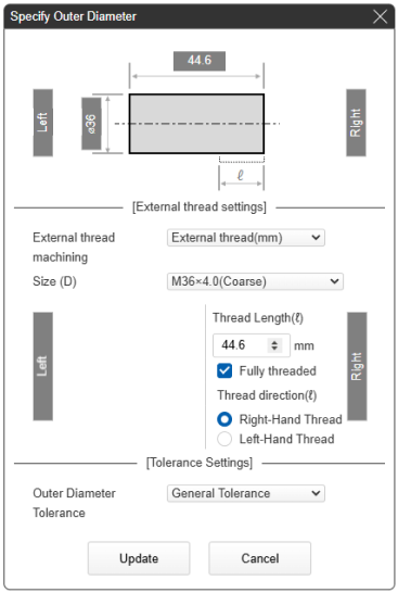
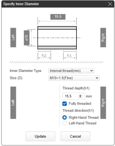
- The [Notes] shown in the red box below describe the applicable thread length/thread depth.
| Example 1) Outer diameter specification: male thread thread length 44.6mm – 4.0 (pitch) x 2.0 = 36.6mm | Example 2) Inner diameter specification: female screw thread depth 15.5mm – (1.0(pitch) × 2.5 + 2.0) = 11.0mm |
 |
 |
Caution
- The thread shape cannot be identified. Set the outer and inner threads.
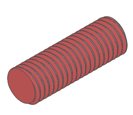
 Machined according to ISO standards (or JIS B 0203)
 Machined according to the model

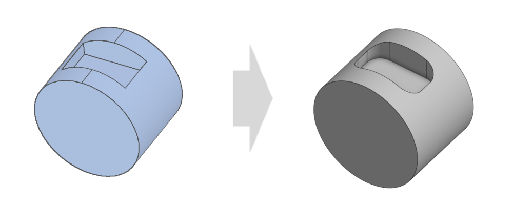
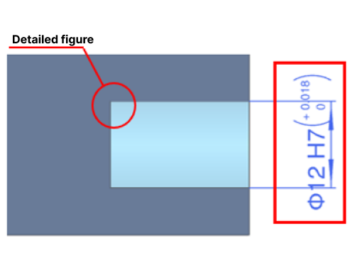
Caution
- The machined curve on the sides of the pocket depends on the tool diameter, which is chosen as small as possible.
- If there are any discrepancies between the model and the finished form, please feel free to let us know.