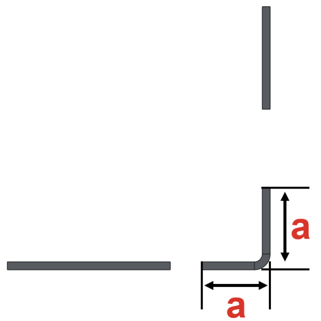
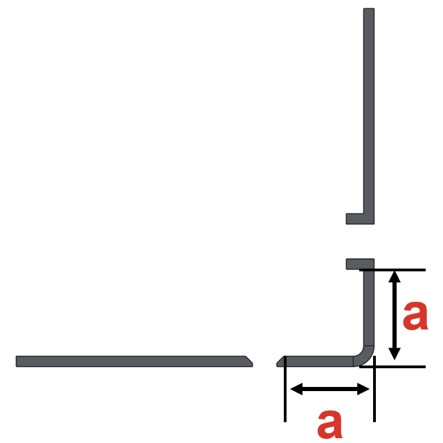
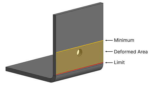
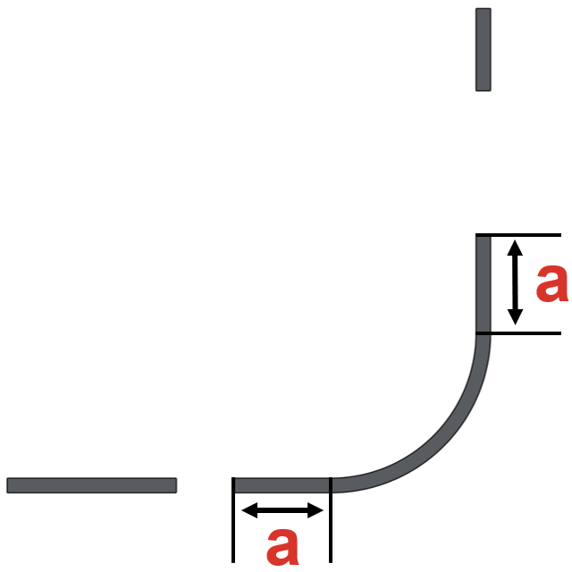
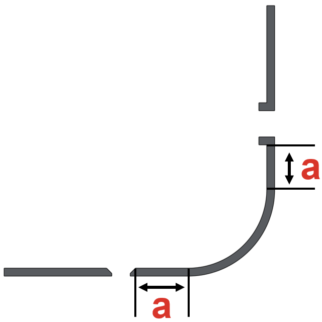
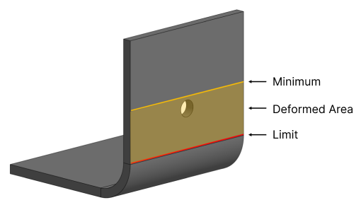
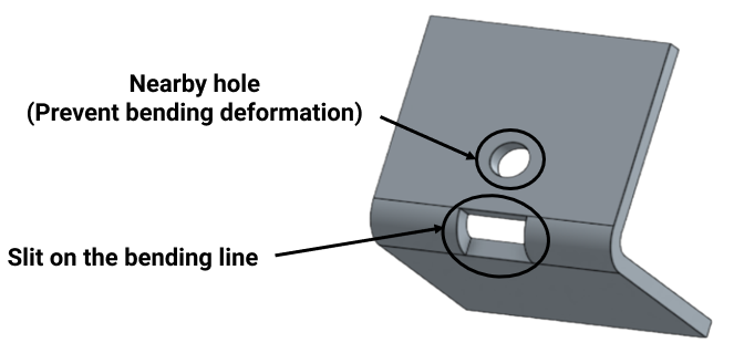
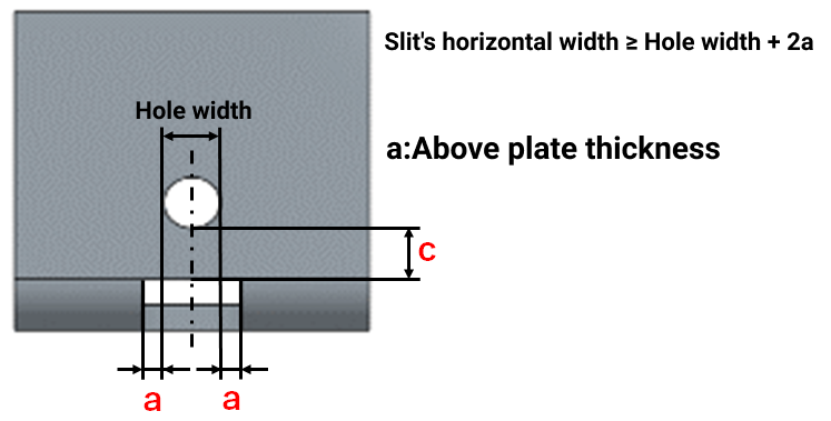
Machining Limits, Size Range
| Plate Thickness | Limita | Limitb | Limitc | ||
|---|---|---|---|---|---|
|
|
|
|||
| 0.8 | 0.8 | 0.8 | 0.5 | 11.5 | 3.0 |
| 1.0 | 1.0 | 1.0 | |||
| 1.2 | 1.2 | 1.2 | 0.6 | ||
| – | 1.5 | 1.5 | 0.7 | ||
| 1.6 | – | 1.6 | 0.8 | ||
| 2.0 | 2.0 | 2.0 | 1.0 | – | |
| 2.3 | – | – | |||
| – | 2.5 | 2.5 | 1.2 | ||
| – | 3.0 | 3.0 | 1.5 | ||
| 3.2 | – | – | |||
| – | 4.0 | 4.0 | 2.0 | ||
| 4.5 | – | – | 2.2 | ||
| – | 5.0 | 5.0 | 2.5 | ||
| 6.0 | 6.0 | 6.0 | 3.0 | ||
| 9.0 | 9.0 | – | 4.0 | ||
| 10.0 | 10.0 | 5.0 | |||
| 12.0 | 12.0 | 6.0 | |||
| 16.0 | – | 8.0 | |||
| Plate Thickness | Limita | Limitb | Limitc | |||||
|---|---|---|---|---|---|---|---|---|
|
||||||||
| 0.1 | 1.0 | – | ||||||
| 0.2 | ||||||||
| 0.3 | ||||||||
| 0.5 | ||||||||
| Plate Thickness | Limita | Limitb | Limitc | |||||
|---|---|---|---|---|---|---|---|---|
|
||||||||
| 0.05 | 0.5 | – | ||||||
| 0.1 | ||||||||
| 0.2 | ||||||||
| 0.3 | ||||||||
| 0.5 | ||||||||
| 0.8 | 0.8 | |||||||
| 1.0 | 1.0 | |||||||
| Plate Thickness | Limita | Limitb | Limitc |
|---|---|---|---|
|
|||
| 0.8 | 10.0 | – | |
| 1.0 | |||
| 1.5 | |||
| Plate Thickness | Limita | Limitb | Limitc | |||
|---|---|---|---|---|---|---|
| PET | Acrylic | Polycarbonate | PVC | |||
| 3.0 | 3.0 | 3.0 | 3.0 | 2.0 | – | |
| 5.0 | 5.0 | 5.0 | 5.0 | |||
| Plate Thickness | Limita | Limitb | Limitc |
|---|---|---|---|
| Aluminum composite sheet (core material: foam polyethylene resin) | |||
| 3.0 | 2.0 | – | |
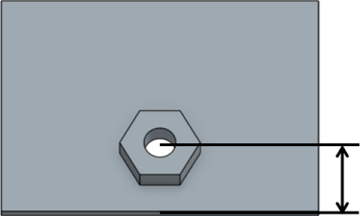
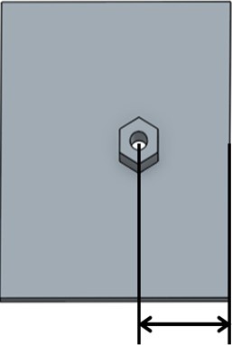
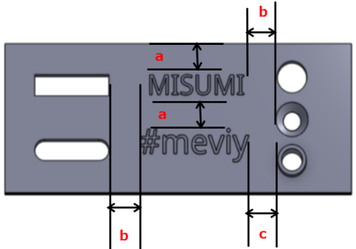
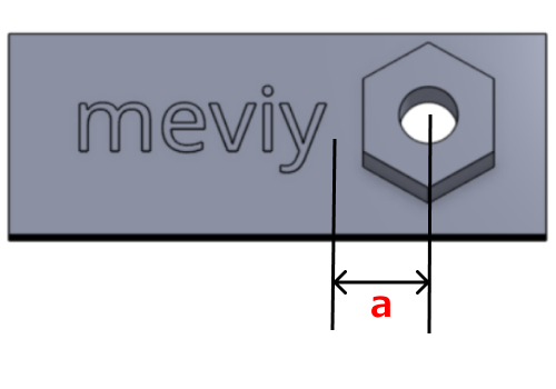
Example
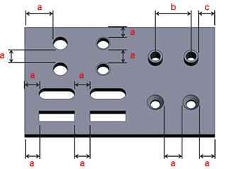
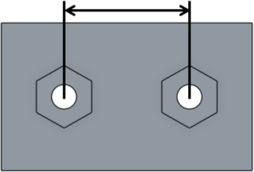
- *The distance between a tapped hole and the edge or between tapped holes is determined by the minimum distance from the outermost diameter of the tapped hole.
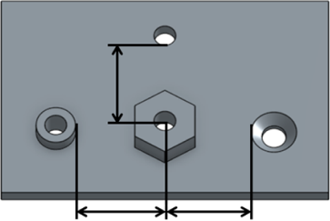
- *The distance between friction drilled/tapped holes is determined from the minimum distance from the center of the hole.
- *The distance between a countersunk hole and the edge or between countersunk holes is determined by the minimum distance from the outermost diameter of the counterbored part.