meviy
MiSUMi
How to use
Search
English
Deutsch
Français
Italiano
Español
Polski
Close
Technical Information
Sheet Metal Parts
Applicable parts/Materials
Shapes Eligible for Quotation
Material, Surface Treatment, Size
Material Standards and Materials Used
Types of Hole Machining
Delivery Options
Material Properties
Surface Treatment Characteristics
Plating / Plated Steel Color Comparison
Types of Paint Color
Specifications for Edge Breaking
Engraving application range
Bending and R-bending with special tools – Overview materials and sizes
Shim Plates
Parts Available for Clear Resin
Parts Eligible for Composite Sheet
Design Guidelines
Basic Modeling Rules
Hole Identification Specifications
Countersink Modeling and Selectable Sizes
Tapped Hole Identification and Selectable Sizes
Friction Drilled/Tapped Holes
About Threaded Insert Specifications
Hanging Holes for Plating/Painting
Modeling Rules for Perforated Metal
Selectable nut sizes
Modeling Rules for Keyhole Type Holes
Range of Machining Limits
Bending Conditions
Sheet Metal Quoting Error Troubleshooting
Accuracy and Machining Specifications
Allowable Dimensional Tolerances
Hole Machining Specifications
Bending Specifications
Appearance of Cut Surfaces
About edge breaking
About Hairline Direction
About pre-finished sheets
About Painted Sheet Metal
Engraving
Perforated Metal Machining Specifications
Clear Resin Specification
Composite Sheet processing specifications
Quality Control
Quality Control of Nut Mounted Products
CNC Milling
Applicable Parts/Materials
Quotable Shapes
Delivery options by material and finish
Material Standards and Materials Used
Delivery Options
Material Properties
Surface Treatment Characteristics
Ineligible Shapes
Heat treatment
Quotable Sizes
Design Guidelines
Shape Disparity between 3D Model and Finish
Points of Note when 3D Modeling
Recognizing Different Types of Hole
Thin-Wall Judgment Logic
Quoting Error Troubleshooting
Accuracy and Machining Specifications
Default General Tolerance Standards
Specifiable Dimensional Tolerances
Specified hole depth tolerance and effective depth tolerance
Specifiable angular tolerance
Hole Information Notation in 3D Screen
Standards for Different Hole and Pocket Types
Rules for Decimal Digit Display on 3D Screen
Engraving specifications
Quality Control
CNC Turning
Applicable parts/Materials
Quotable Shapes
Shapes Not Supported for Automatic Quotation
Delivery options by material and finish
Delivery Options
Material Properties
Surface Treatment Characteristics
Material Standards and Materials Used
Design Guidelines
Turning Parts Recognition Conditions
Rules for Dimension Notation on 3D Viewer
Difference in Shapes Between the 3D Model and the Finished Product
Thin-Wall Judgement Logic
Example Errors for CNC Turning
Accuracy and Machining Specifications
Default General Tolerance Standards
Specifications for External Thread and Internal Thread, Keyways, Holes and Pockets
Specifiable Dimensional Tolerances
Rules for Decimal Digit Display on 3D Viewer
Engraving specifications
Quality Control
Accuracy and Machining Specifications
How to use
Before You Begin
What is meviy?
Procedure for Using the meviy Platform
Parts Available for Order from meviy
Uploadable CAD File Formats
Recommended Operating Environment
Creating an Account
Logging In / Logging Out
User Menu
Automatic hole/inner diameter type Recognition
SOLIDWORKS
iCAD
User Settings (Optional)
Managing Projects
Uploading 3D Data
Viewing the Project List Screen
Organizing Projects
Deleting and Restoring Projects (Trash Function)
Quotation conditions settings
[Sheet Metal Parts] Quotation Settings
Quotation Procedure
Viewing the 3D Viewer Screen
How to Use the 3D Viewer
Changing Hole Information
Setting Basic Information
Changing Font Sizes
Adding/Removing Dimensions
Splitting Grouped Holes
Set engraving
Measuring 3D models
Confirm(issue part number)/check/change the quotation
Auto-Fixing of Plate Thicknesses of Bends
Keyboard Operations
Information about manual quotation
[CNC Milling] Quotation Settings
Quotation Procedure
Viewing the 3D Viewer Screen
How to Use the 3D Viewer
Setting Basic Information
Changing Hole Information
Adding/Deleting Dimensions and Dimensional Tolerances
Adding Dimensions and Dimensional Tolerances in batch
Add/delete angular dimensions and angular tolerances
Set Surface Roughness, Grind, and Finefinish
Set engraving
Splitting Group Holes
Set datum and geometric tolerances
Changing Font Sizes
Change a Design's Origin
Measuring 3D models
Confirming Approvals
Generate Mirror Parts
Confirm(issue part number)/check/change the quotation
Keyboard Operations
Information about manual quotation
Select Heat Treatment (Through Hardening)
[CNC Turning] Quotation Settings
Quotation Procedure
Viewing the 3D Viewer Screen
How to Use the 3D Viewer
Setting Basic Information
Setting Hole Information
Adding / Deleting Dimensions and Dimensional Tolerances
Setting Outer Diameter Information
Setting Inner Diameter Information
Setting Slotted Holes/Keyways
Setting Surface Roughness
Setting Surface Roughness of unspecified area
Select Heat Treatment (Through Hardening or Surface Hardening)
Set datum and geometric tolerances
Set engraving
Splitting Group Holes
Changing Font Sizes
Changing a Design’s Origin
Measuring 3D models
Confirming Approvals
Confirming(Issue part number)/Check/Change the quotation
Keyboard Operations
Information about manual quotation
User Settings (Turning Parts)
Order
Orders
Ordering procedure from the MISUMI website
Ordering from meviy
Changing or Canceling an Order
Downloading 2D Drawing, Quotes and Parts Lists
Repeat Orders
Payment Methods
Exporting the Order Confirmation as a PDF
Convenient Features
Confirming your purchase history
Import and export user settings
Displaying the revision history for a part number
Publish an Issued Part Number/Share a Project
To use the search window
Controlling Models with the Mouse
Enter the order numbers
HELP
How to use
Quotation conditions settings
[CNC Turning] Quotation Settings
Setting Outer Diameter Information
Setting Outer Diameter Information
Update Outer Diameter Information
Outer Diameter Information Designation Dialog (Outer Diameter/Outer-most Diameter)
Thread and Tolerance Settings
Update Outer Diameter Information
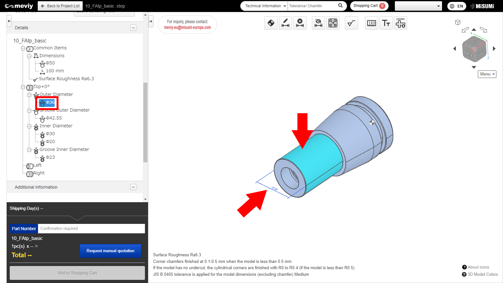
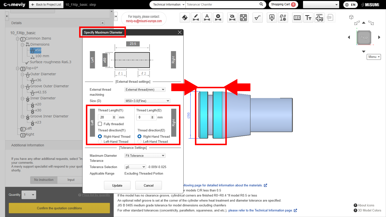
You can select the target from Details or the 3D viewer, and change the outer diameter information.
1. Double click either “Value” in Details, or the applicable “Dimensions” or “Face” from the 3D viewer.
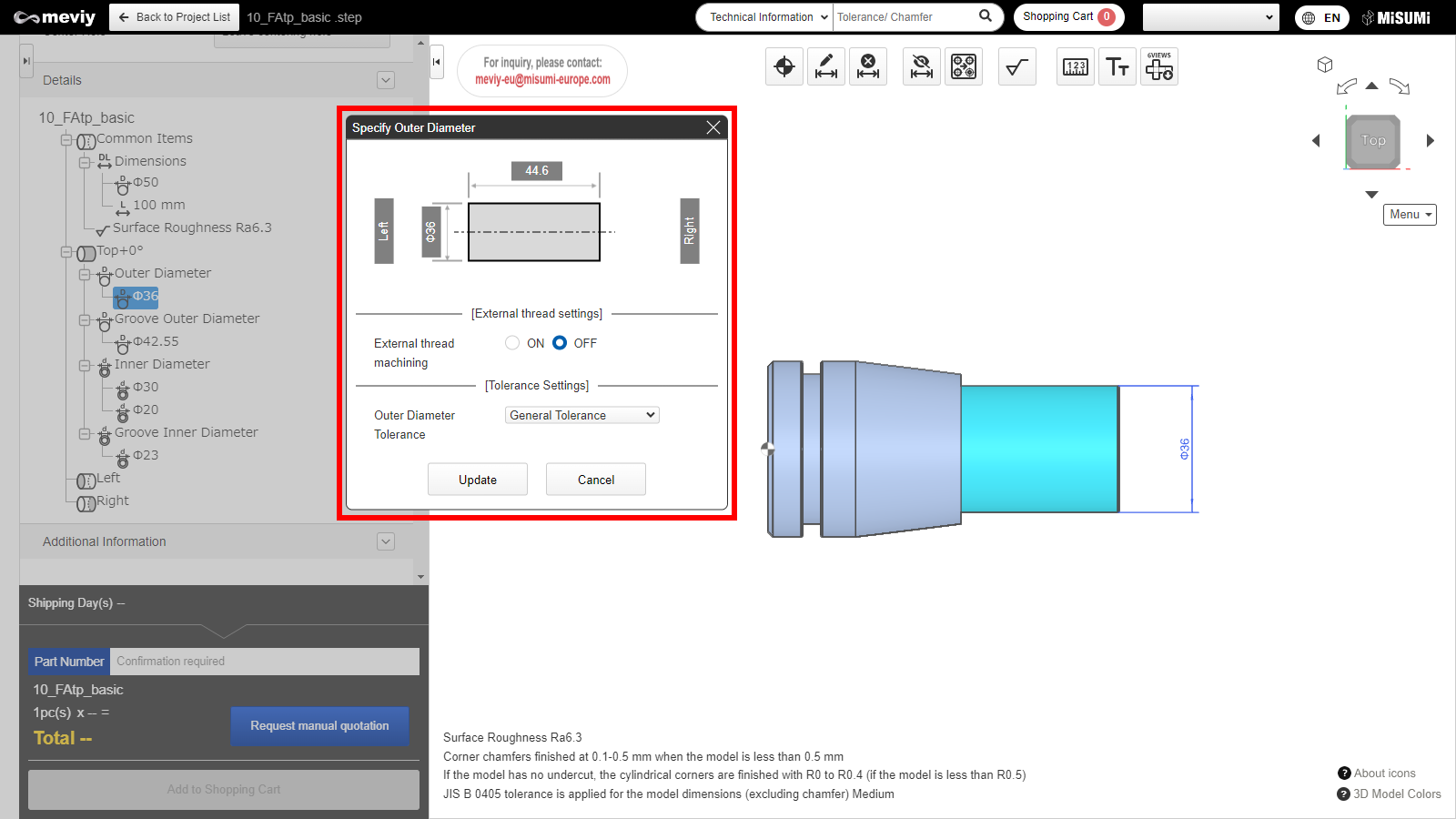
2. Selecting this changes the model position to the TOP orientation direction and displays a dialog.
3. Configuration of “Thread Settings” and “Tolerance Settings” is possible.
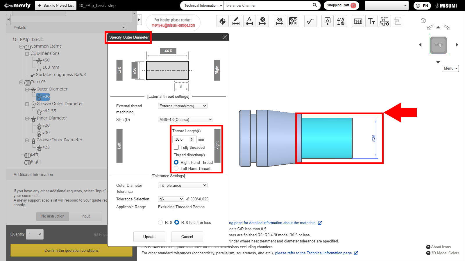
Outer Diameter Information Designation Dialog (Outer Diameter/Outer-most Diameter)
The dialog has two types—”Outer Diameter” and “Outer-most Diameter.”
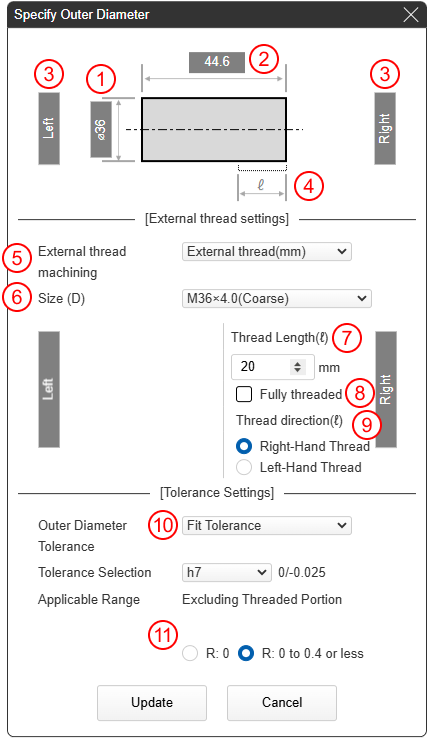
Outer Diameter Information Designation
Machining is only possible from one side, so “Length” settings from one side are displayed.
*Areas that can have “Length” adjusted are highlighted in light blue
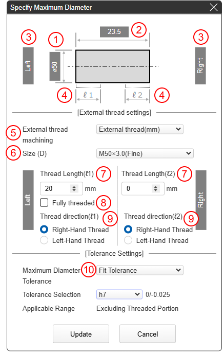
Outer-most Diameter Information Designation
Machining is possible from both sides, so “Length” settings from both sides are displayed.
*Areas that can have “Length” adjusted are highlighted in light blue
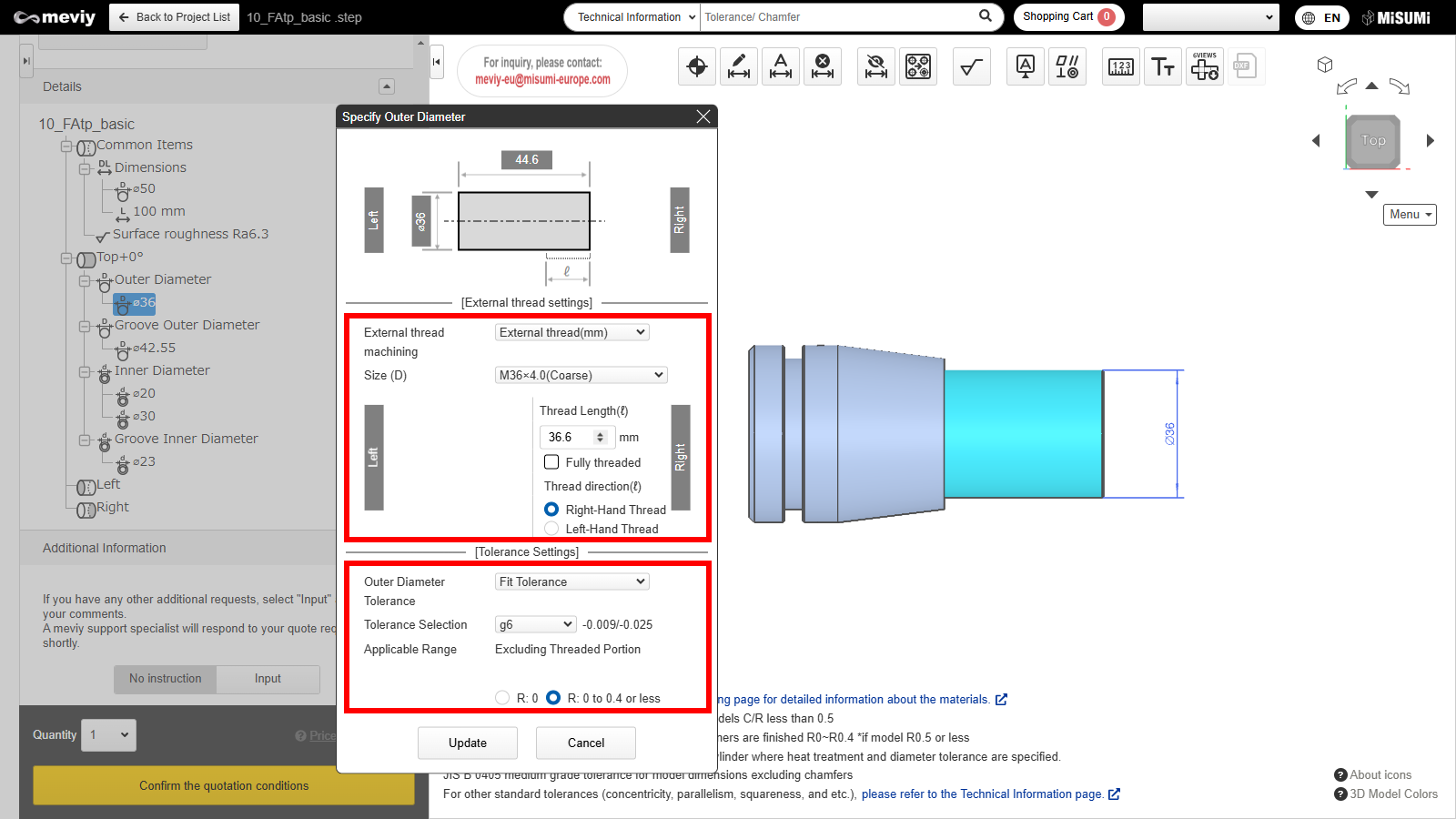
Thread and Tolerance Settings
Details of the dialog are as follows.
Outer-most Diameter Information Designation
(1) Highlighted section “Diameter” information
(2) Highlighted section “Length” information
(3) 3D viewer left side/right side linkage
(4) “Length” that can be set from the left side/right side
Thread Settings
(5) “External Thread (mm)/External Thread (inch)” can be selected.
(6) Applicable size can be selected.
(7) Threads for (4) can be set.
(8) All threads can be set.
(9) Left-hand/right-hand threads for (4) can be set.
*External Thread (inch) is only compatible with right-hand threads.
Tolerance Settings
(10) “General Tolerance,” “Fit Tolerance,” “Tolerance on both sides,” “Tolerance on one side” can be selected.
*Tolerances apply to the area excluding the threaded part.
Outer Diameter Information Designation
(1) Highlighted section “Diameter” information
(2) Highlighted section “Length” information
(3) 3D viewer left side/right side linkage
(4) “Length” that can be set
Thread Settings
(5) “External Thread (mm)/External Thread (inch)” can be selected.
(6) Applicable size can be selected.
(7) Threads for (4) can be set.
(8) All threads can be set.
(9) Left-hand/right-hand threads for (4) can be set.
*External Thread (inch) is only compatible with right-hand threads.
Tolerance Settings
(10) “General Tolerance,” “Fit Tolerance,” “Tolerance on both sides,” “Tolerance on one side” can be selected.
*Tolerances apply to the area excluding the threaded part.
(11) You can specify the radius of the cylindrical corner.
*Please refer
here
for notes on finishing.
Recently viewed articles
↑