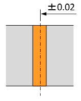
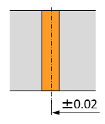
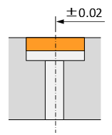
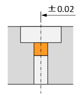
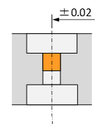
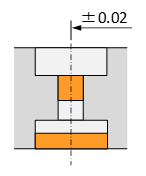
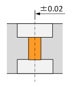
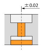
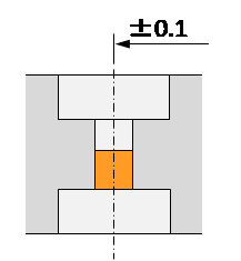
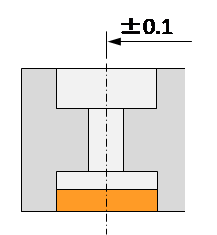
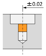
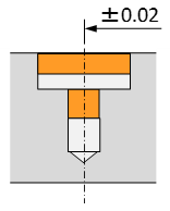
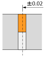
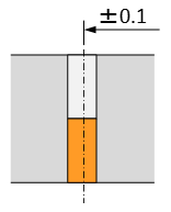
Specifiable Dimensional Tolerances

Dimensional Tolerances

When uploading 3D CAD data, you can specify any dimensions/tolerances for parts where dimensions and tolerances are not displayed.

The minimum specifiable value ranges for tolerances depends on the combination of shape elements.

Depending on other settings, in-range precision may not be covered by the service.

Shape Elements and Minimum Value Ranges for Tolerances

[mm]

Steel, Pre-Hardened Steel, Stainless Steel, Aluminum
Shape Element ①/Shape Element ②Blank SurfacePocketsPrecision Holes/Other Hole TypesPrecision Slotted HolesStraight Holes (No Precision)
Tapped Holes/Countersunk Holes/Slotted Holes
Blank Surface *10.10.040.040.040.2
Pockets *2
Precision Holes/Other Hole Types
Precision Slotted Holes
Straight Holes (No Precision)
Tapped Holes/Countersunk Holes/Slotted Holes

*If the range is less than 0.2, Trivalent Chromate (clear) is not available as a surface treatment via the service.

[mm]

Resin
Shape Element ①/Shape Element ②Blank SurfacePocketsPrecision Holes/Other Hole TypesPrecision Slotted HolesStraight Holes (No Precision)
Tapped Holes/Countersunk Holes/Slotted Holes
Blank Surface *10.10.040.040.040.2
Pockets *2
Precision Holes/Other Hole Types
Precision Slotted Holes
Straight Holes (No Precision)
Tapped Holes/Countersunk Holes/Slotted Holes

[mm]

  • Polished flat bar
  • (EN 1.0038 equiv. (flat bar)​, EN 1.1191 equiv. (flat bar)​, EN 1.4301 equiv. (flat bar), EN AW-6063 equiv. (flat bar))
Shape Element ①/Shape Element ②Blank SurfacePocketsPrecision Holes/Other Hole TypesPrecision Slotted HolesStraight Holes (No Precision)
Tapped Holes/Countersunk Holes/Slotted Holes
Blank Surface *10.20.20.20.20.2
Pockets *2
Precision Holes/Other Hole Types
Precision Slotted Holes
Straight Holes (No Precision)
Tapped Holes/Countersunk Holes/Slotted Holes
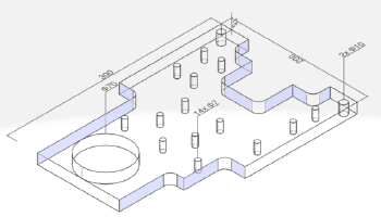
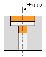
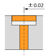
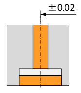
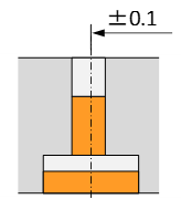
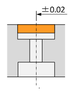
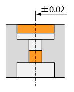
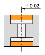
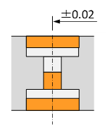
*1 Blank Surface: The entire surface used for external dimensions.
*1 Blank Surface
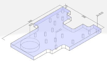
*2 Pocket: A cutting surface other than a blank surface.
*2 Pocket

Application conditions for overlapping dimensions

  • Duplicate dimension checks are performed for meviy milled products.
  • Duplicate dimensions cannot be set to avoid duplicate instructions.
  • Logic (1)
  • Holes of the same diameter that exist on the same plane are treated as holes of the same group.
  • If you specify dimensional tolerances for holes, or holes and blank and pocket surfaces, the dimensions are also applied to the holes on the same coax in the same group, and the duplicate is determined.

When dimensional tolerances are specified for ‘H-001’, they shall also apply to ‘H-002’ on the same axis and within the same group.

If you want to specify different dimension tolerances for H-001 and H-002, you first need to split the group.

Logic (2)

Dimensions that can be expressed by calculating other dimensions are judged to be duplicated.

When dimensions are set to ‘50’ and “150”, the dimension ‘100’ – which can be expressed as 150 minus 50 – will be flagged as a duplicate.

Visualization of features whose dimensions are covered

Dimensions are indicated by highlighting or a dotted line.

■How to view 3DViewer

  • Click on a dimension to highlight the hole to which the dimension is applied.
  • (In the image, the hole in the bottom left and the hole in the upper left)

■How to view a simple 2D diagram

Dimensions are applied to holes, which are indicated by a dotted line.

Important Points when Specifying Dimensional Tolerances for Precision Holes

As mentioned above under “Dimensional Tolerance”, when specifying dimensional tolerance for a precision hole, the minimum tolerance value (range) is generally 0.04.

However, there is an exception where the minimum tolerance value (range) is 0.2.

*The orange area is the effective depth range of a precision hole.

0-Step/1-Step Holes (Counterbored Holes), Blind
0-Step/1-Step hole (counterbored hole), blind
⇒ Minimum tolerance value (range): 0.04
0-Step Holes, Through
0-Step hole, through
Dimensional tolerance specification on the effective depth side ⇒ minimum tolerance value (range): 0.04
0-Step hole, through
Dimensional tolerance specification on the effective depth side and opposite side ⇒ minimum tolerance value (range): 0.2
0-Step hole, through
Dimensional tolerance specification on effective depth full-length holes ⇒ minimum tolerance value (range): 0.04
1-Step Holes (Counterbored), Through
1-Step hole (counterbored), through 1-Step hole (counterbored), through
Dimensional tolerance specification on the upper side ⇒ minimum tolerance value (range): 0.04
1-Step hole (counterbored), through
If the lower step is the total length of the effective depth, lower step side dimensional tolerance specification ⇒ minimum tolerance value (range): 0.04
1-Step hole (counterbored), through
If the lower step is not the total length of the effective depth, lower step side dimensional tolerance specification ⇒ minimum tolerance value (range): 0.2
2-Step Holes
2-Step hole 2-Step hole
Dimensional tolerance specification on the side of the step with a set effective depth ⇒ minimum tolerance value (range): 0.04
2-Step hole 2-Step hole
Dimensional tolerance specification on the central step effective depth and opposite side ⇒ minimum tolerance value (range): 0.04
2-Step hole 2-Step hole
Dimensional tolerance specification on the central step effective depth and opposite side ⇒ minimum tolerance value (range): 0.04
2-Step hole
Dimensional tolerance specification on the central step effective depth and opposite side ⇒ minimum tolerance value (range): 0.2
2-Step hole
Dimensional tolerance specification on steps with set effective depth and opposite side ⇒ minimum tolerance value (range): 0.2

Recently viewed articles