- HELP
- Technical Information
- CNC Milling
- Design Guidelines
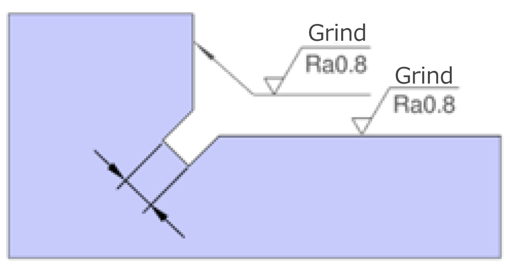
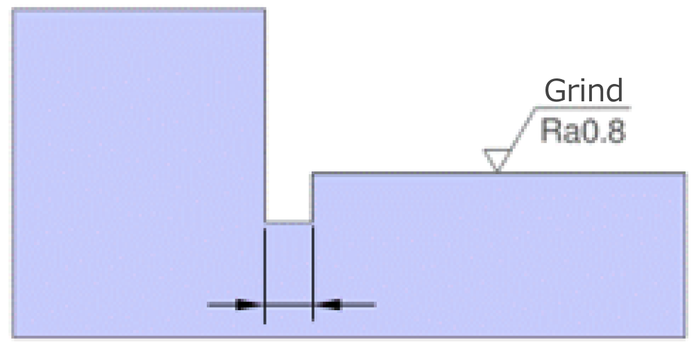
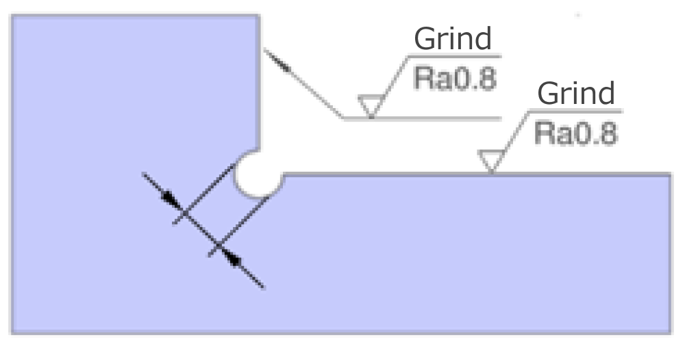
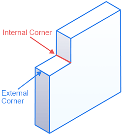
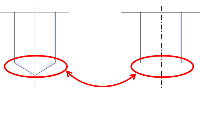
- Shape Disparity between 3D Model and Finish
Shape Disparity between 3D Model and Finish
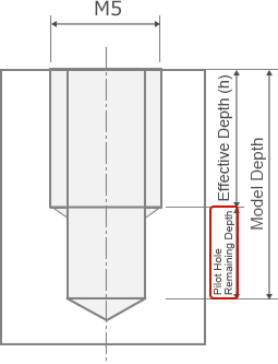 |
| Pilot-hole depth reference value = pitch × 2.5 + 2 mm |
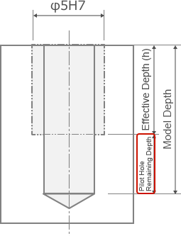 |
| Pilot-hole remaining depth reference value = 2.7 mm |