- HELP
- Technical Information
- Sheet Metal Parts
- Accuracy and Machining Specifications
- Bending Specifications
Bending Specifications
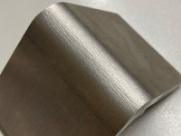
| No. | Standard Part | Standard Value | Example |
|---|---|---|---|
| 1 | Bend angle tolerance |
|  |
| 2 | Inner radius (r) | Plate thickness (reference value) | |
| 3 | Outer radius (R) | R = plate thickness × 2 (reference value) |
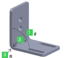
| No. | Standard Part | Standard Value | Example |
|---|---|---|---|
| 1 | Bend angle tolerance |
|
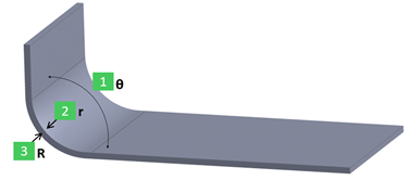 |
| 2 | Inner R | Modeling dimension (Reference value) | |
| 3 | Outer R | Inner R+Plate thickness (Reference value) |
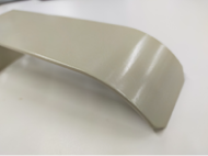
| Standard Value | Example |
|---|---|
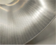
| As shown in the right hand example, bulging/protrusions of about 15% of the plate thickness can occur on each side. |  |
| Standard Value | Example | ||||||||||||
|---|---|---|---|---|---|---|---|---|---|---|---|---|---|
| As shown in the right hand example, defects have occurred in the bent die. |  |
||||||||||||
| Since it is processed as FR bending (feed bending), die marks will be left on the R bending part. |
|
||||||||||||
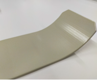
| Standard Value | Example |
|---|---|
| EN AW−5052 equiv. would have a slight crack when bent due to its material properties. |
|