Quality Control
| Cut surface | Marks from the hanging jig used during the application of the painting coat | |
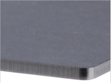
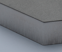
With laser processing The cut surface will have a smooth edge. |
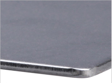
With turret punch press machining The machining surface will have a smooth curved shape. |
 |
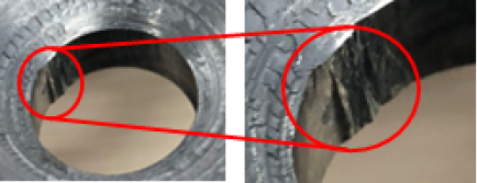
| Burring in the pulling direction | Damage caused by bending | Protrusion from bending |
 |
 |
 |
 | 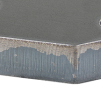 |
| EN 1.4301 equiv.(NO.1) plate thickness 12㎜ | EN 1.0038 equiv. plate thickness 16㎜ |
 | 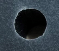 |
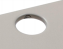
| Unevenness inside the hole | Hole shape distored on the back side |
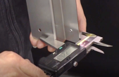
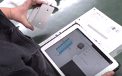
| View of inspection (1) | View of inspection (2) |
 |
 |
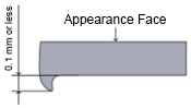
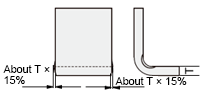
| Example | Example of non-applicable dimensions |
 |
 |
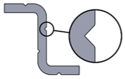
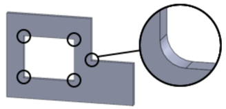
| Clear resin internal angle (R) |
 |