- HELP
- Technical Information
- Welded Sheet Metal
- Applicable Parts/Materials
- Unsupported shapes
Unsupported shapes
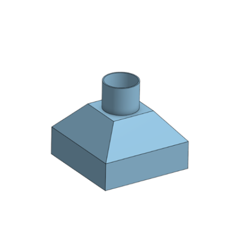
| 1 | Ducts / Hoppers |
 |
|
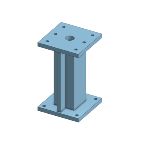
| 2 | Frames or Supports That Include Steel Pipes or Structural Steel |
 |
|
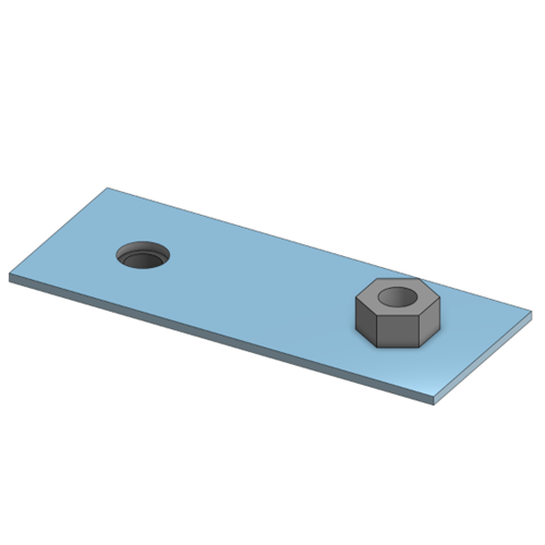
| 3 | Models That Include Non–Sheet-Metal Components Such as Nuts |
 |
|
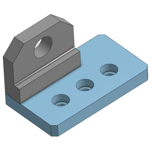
| 4 | Shapes That Include Non–Sheet-Metal Machined Parts |
 |
|