- HELP
- How to use
- Before You Begin
- Automatic hole / inner diameter type Recognition
- Automatic Recognition of hole / inner diameter type from CAD Hole Attributes
Automatic Recognition of hole / inner diameter type from CAD Hole Attributes
You can link the hole attributes created by the Hole command in the target CAD software to reflect the hole and inner diameter type in meviy.
Setup Method
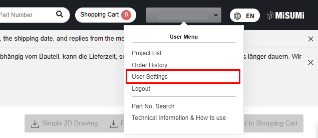
STEP1:
STEP2:
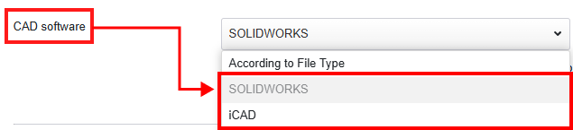
Select the CAD software you want to use from the drop-down menu.
STEP3:
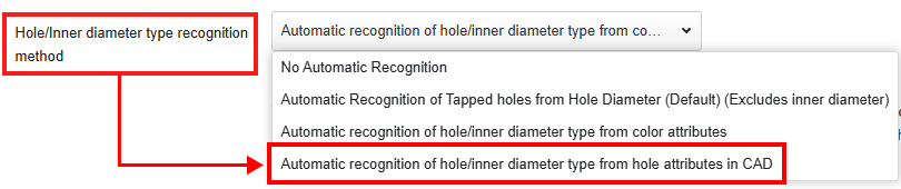
Under How to Recognize Hole/Inner Diameter Type, select “Automatic recognition of hole/inner diameter type from hole attributes in CAD
” from the drop-down.
STEP4:
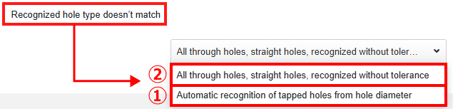
You can specify how the hole type is recognized when the hole attributes do not match.
Select one of the following options from the drop-down menu:
①Automatic recognition of tapped holes from hole diameter
If the hole attributes are not linked, the threaded hole is automatically recognized based on the hole diameter.
Automatic Recognition of Tapped holes from Hole Diameter
②All through holes, straight holes, recognized without tolerance
If the hole attributes are not linked, it is recognized as a straight hole or a through hole.
STEP5:
Click “Save Settings” at the bottom of the page.
After uploading the data:
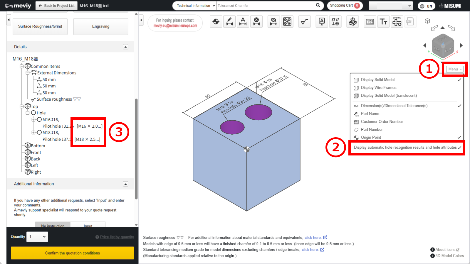
(1) Hover the mouse over [ Menu
] in the 3D viewer.
(2) Click [ Display automatic hole recognition results and hole attributes ].
(3) The hole list in the tree view will display information about the linked hole attributes.
Caution
Restrictions apply to the types of holes and boreholes that can be linked from the ‘Hole’ attribute.Please refer to the following precautions and adjust the meviy settings as required.
-
The effective depth of each hole is independent and reflects the user’s settings.
Set the effective depth for each item using the following user settings. - Quotation Settings for Machined Plates Tapped Holes
- Quotation Settings for Turning Parts Tapped Holes
- Quotation Settings for Machined Plates Precision Holes
- Quotation Settings for Turning Parts Precision Holes
-
This function does not link the machining direction.If the pilot hole is penetrated, check the machining direction.
Tip
- For the table showing the correspondence between CAD commands and hole commands, please refer to the following details.
- →Automatic hole/inner diameter type Recognition > “SOLIDWORKS“
- →Automatic hole/inner diameter type Recognition > “iCAD“
-
There are limitations to the CAD data that can be linked to hole attributes.Please refer to the table below, ‘3D CAD format for linking hole attributes‘.
Notes
- See below for more information.
- → CNC Milling > Recognizing Different Types of Hole
- → CNC Turning > Specifications for External Thread and Internal Thread, Keyways, Holes and Pockets
- → Sheet Metal Parts > Tapped Hole Identification and Selectable Sizes
・3D CAD format for linking hole attributes
| CAD softwares | Native | Intermediate format(Parasolid) | ||
|---|---|---|---|---|
| (.sldprt)(.icd) | .x_t | .x_b | .xmt_txt | |
| SOLIDWORKS | 〇 | – | – | – |
| iCAD SX | 〇 | – | – | – |
Caution
For models and CAD formats that are not supported by meviy, there is no guarantee of automatic hole/inner diameter type recognition.
| Modeling methods | Cooperation | Description |
|---|---|---|
| Hole commands for each CAD | 〇 | Since hole information is available, it can be linked correctly. |
| Customised hole commands | △ | Due to special settings, proper linkage may not be possible. |
| Holes created using extruded cuts or similar methods without the Hole command | – | Not supported because no hole attributes are defined. |