- HELP
- How to use
- Before You Begin
- Automatic hole / inner diameter type Recognition
Automatic hole / inner diameter type Recognition
It can automatically recognize taps from the hole diameter, colored holes, or hole attributes for each CAD, and reflect them in meviy.
What are the hole and inner diameter types? Round: Screw (internal thread) in the centre of the shaft; precision hole.
Hole Type Linkage / Automatic Recognition of hole/inner diameter type from CAD Hole Attributes

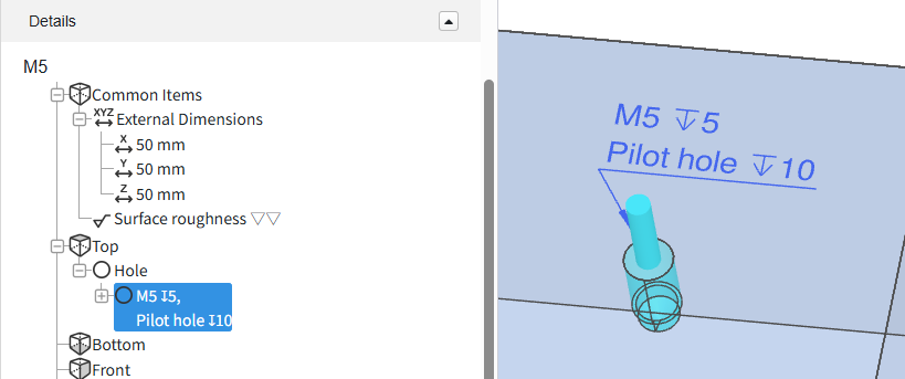
STEP1:
STEP2:
STEP3:
Setup Method:
Caution
Restrictions apply to the types of holes and boreholes that can be linked from the ‘Hole’ attribute.-
The effective depth of each hole is independent and reflects the user’s settings.
Set the effective depth for each item using the following user settings. - Quotation Settings for Machined Plates Tapped Holes
- Quotation Settings for Turning Parts Tapped Holes
- Quotation Settings for Machined Plates Precision Holes
- Quotation Settings for Turning Parts Precision Holes
-
This function does not link the machining direction.If the pilot hole is penetrated, check the machining direction.
Tip
- For the table showing the correspondence between CAD commands and hole commands, please refer to the following details.
- →Automatic hole/inner diameter type Recognition > “SOLIDWORKS“
- →Automatic hole/inner diameter type Recognition > “iCAD“
-
There are limitations to the CAD data that can be linked to hole attributes.Please refer to the table below, ‘3D CAD format for linking hole attributes‘.
Notes
- See below for more information.
- → CNC Milling > Recognizing Different Types of Hole
- → CNC Turning > Specifications for External Thread and Internal Thread, Keyways, Holes and Pockets
- → Sheet Metal Parts > Tapped Hole Identification and Selectable Sizes
| CAD softwares | Native | Intermediate format(Parasolid) | ||
|---|---|---|---|---|
| (.sldprt)(.icd) | .x_t | .x_b | .xmt_txt | |
| SOLIDWORKS |
〇 |
– |
– |
– |
| iCAD SX |
〇 |
– |
– |
– |
Caution
For models and CAD formats that are not supported by meviy, there is no guarantee of automatic hole/inner diameter type recognition.| Modeling methods | Cooperation | Description |
|---|---|---|
| Hole commands for each CAD | 〇 | Since hole information is available, it can be linked correctly. |
| Customised hole commands | △ | Due to special settings, proper linkage may not be possible. |
| Holes created using extruded cuts or similar methods without the Hole command | – | Not supported because no hole attributes are defined. |
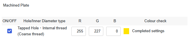
Color Attributes Linkage / Automatic Recognition of hole/inner diameter type from Color Attributes
The colour displayed on the side of the hole in the model is automatically recognised, and the hole and inner diameter type can be reflected in meviy by matching it with the pre-registered value.
STEP1:
STEP2:
STEP3:
Setup Method:
Caution
Restrictions apply to the types of hole and inner diameter that can be linked from the colour attribute.-
The effective depth of each hole is independent and reflects the user’s settings.
Set the effective depth for each item using the following user settings. - Quotation Settings for Machined Plates Tapped Holes
- Quotation Settings for Turning Parts Tapped Holes
- Quotation Settings for Machined Plates Precision Holes
- Quotation Settings for Turning Parts Precision Holes
-
This function does not link the machining direction.If the pilot hole is penetrated, check the machining direction.
Tip
-
There are limitations to the CAD data that can be linked to colour attributes.Please refer to the table below, ‘3D CAD format for colour attributes‘.
Notes
- See below for more information.
- → CNC Milling > Recognizing Different Types of Hole
- → CNC Turning > Specifications for External Thread and Internal Thread, Keyways, Holes and Pockets
- → Sheet Metal Parts > Tapped Hole Identification and Selectable Sizes
| CAD softwares | Native | Intermediate format(Parasolid) | ||
|---|---|---|---|---|
| (.sldprt)(.icd) | .x_t | .x_b | .xmt_txt | |
| SOLIDWORKS |
〇 |
〇 |
〇 |
– |
| iCAD SX |
〇 |
〇 |
〇 |
〇 |
Caution
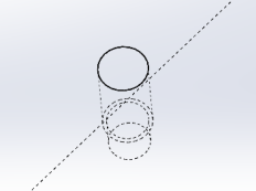
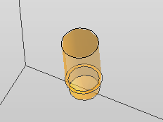
The automatic recognition of hole/inner diameter type from color attribute is not guaranteed for models created with non-compatible CAD systems or formats.Automatic Recognition of Tapped holes from Hole Diameter
| CAD softwares , (ø)mm | ||||||
|---|---|---|---|---|---|---|
|
Tap Size
(Coarse) |
Creo onshape SW(A) | Solid Edge
IRON |
NX |
CATIA V5
Inventer |
SW(B)
iCAD SX |
Fusion |
| M5 | 4.2 | 4.2 | 4.13 | 5 | 4.23 | |
STEP1:
STEP2:
STEP3:
Setup Method:
Caution
When using this feature, please make sure to review the hole auto-recognition results in meviy.- Customized pilot hole diameters are not automatically recognized.
- Original hole attribute information assigned in 3D CAD is not carried over.
-
The effective depth of each tapped hole is not linked; user-defined settings are applied instead.
Set the effective depth for each item using the following user settings. - Quotation Settings for Machined Plates Tapped Holes
- Quotation Settings for Turning Parts Tapped Holes
-
This function does not link the machining direction.If the pilot hole is penetrated, check the machining direction.
Notes
- See below for more information.
- → CNC Milling > Recognizing Different Types of Hole
- → CNC Turning > Specifications for External Thread and Internal Thread, Keyways, Holes and Pockets
- → Sheet Metal Parts > Tapped Hole Identification and Selectable Sizes
| Tapped Hole Identification Settings:CAD softwares | ||||||
|---|---|---|---|---|---|---|
|
Tap Size
(Coarse) |
Creo
onshape
SW(A) |
Solid Edge
IRON |
NX |
CATIA V5
Inventer |
SW(B)
iCAD SX |
Fusion |
| M2 | 1.6 | 1.6 | 1.57 | 2 | 1.62 | |
| M2.5 | 2.05 | 2.05 | 2.01 | 2.5 | 2.08 | |
| M3 | 2.5 | 2.5 | 2.46 | 3 | 2.53 | |
| M4 | 3.3 | 3.3 | 3.24 | 4 | 3.33 | |
| M5 | 4.2 | 4.2 | 4.13 | 5 | 4.23 | |
| M6 | 5 | 5 | 4.92 | 6 | 5.04 | |
| M8 | 6.8 | 6.8 | 6.65 | 8 | 6.78 | |
| M10 | 8.5 | 8.5 | 8.38 | 10 | 8.53 | |
| M12 | 10.2 | 10.3 | 10.11 | 12 | 10.27 | |
| M14 | 12 | 12.1 | 11.84 | 14 | 12.02 | |
| M16 | 14 | 14 | 13.84 | 16 | 14.02 | |
| M18 | 15.5 | 15.5 | 15.29 | 15.5 | 15.52 | |
| M20 | 17.5 | 17.5 | 17.29 | 17.5 | 17.52 | |
| M22 | 19.5 | 19.5 | 19.29 | 19.5 | 19.52 | |
| M24 | 21 | 21 | 20.75 | 21 | 21 | |
No Automatic Recognition
Caution
・With this setting, cylindrical holes are recognized as follows:- → Sheet metal processing: All through holes
- → Machining: Straight holes without tolerances