- HELP
- Technical Information
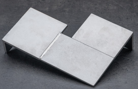
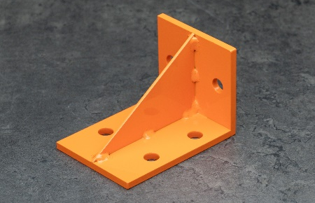
- Welded Sheet Metal
- Accuracy and Specifications
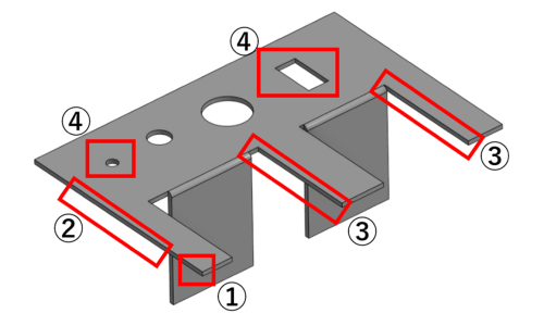
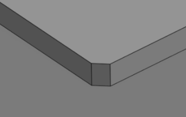
- About Edge Breaking (Welded Sheet Metal parts)
About Edge Breaking (Welded Sheet Metal parts)
| Model Example | Part Example | Standard Value | |
|---|---|---|---|
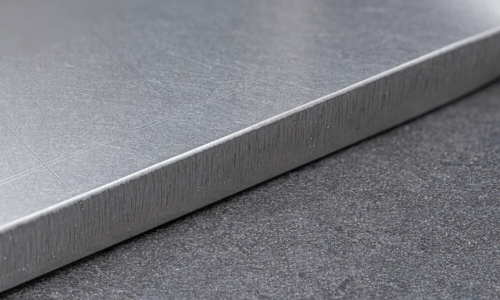
| Light Edge Breaking |
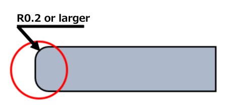
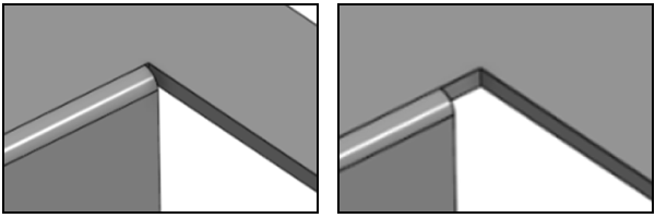
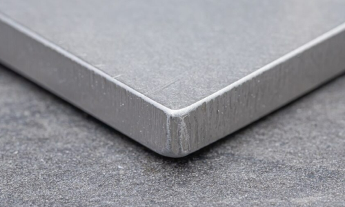
C/R Edge Breaking
Option Name: “All Around R0.2 or Larger / Corner C1” |
||
 |
|
Not Available |
|
|
 |
 |
|
|
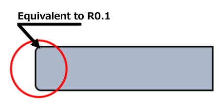
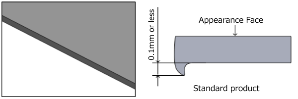
No burrs or flash of 0.1 mm or larger | Finish burrs and flash to approx. R0.1 | |
|
No burrs or flash of 0.1 mm or larger | Finish burrs and flash to approx. R0.1 | |
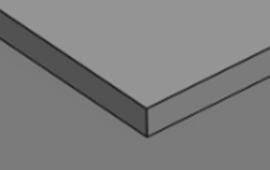
EN 1.4301 equivalent (2B), thickness 6.0 mm
EN 1.4301 equivalent (2B), thickness 6.0 mm