- HELP
- Technical Information
- Welded Sheet Metal
- Design Guidelines
- Determination and Recognizable Size of Weld Locations
Determination and Recognizable Size of Weld Locations
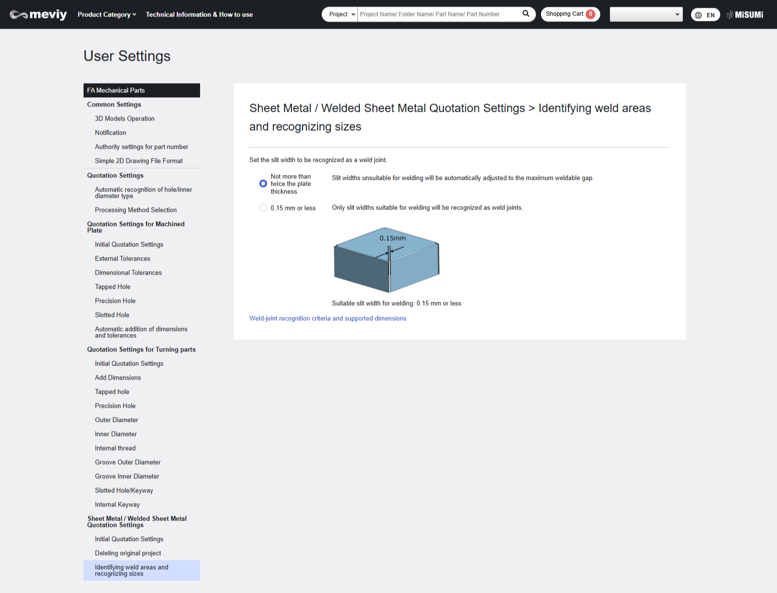
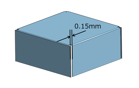
- In the Sheet Metal Weld service, as a general rule, areas where the distance between elements in the 3D model is 0.15 mm or less are detected and determined to be weld locations.
- For single-solid models commonly used for welded structures (such as boxes and covers), you can choose between two thresholds for identifying weld locations. See below for the areas identified as weld locations and those that are not, depending on the model.
Areas identified as weld locations (3D model composed of a single solid)
Select from the user setting “Weld location recognition threshold”
| Within twice the Plate Thickness | Slit widths unsuitable for welding are automatically corrected to the maximum weldable spacing. (Default) |
| 0.15 mm or less | Only slits with widths suitable for welding are recognised as weld locations. |
■Settings for the threshold for automatic recognition of weld locations
3D models composed of a single solid
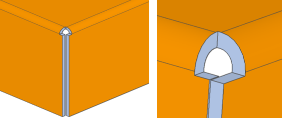
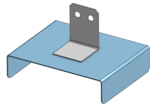
For shapes formed by a single sheet metal part, areas with gaps of 0.15mm or less are recognized as welded joints.
Tip
- For shapes formed from a single sheet metal part, slit sections within 0.15mm are judged as weld points. Welding exemption cannot be selected.For areas where welding is not required, please leave a gap greater than or equal to the threshold selected in the user settings above.
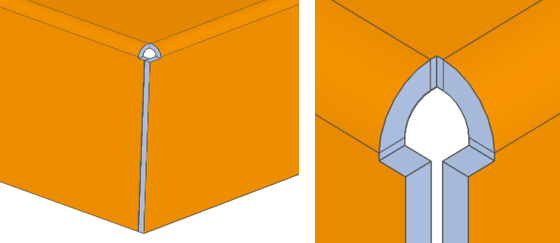
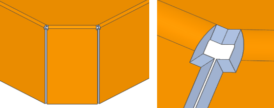
- For the box shown in the right diagram, the corners of the box are also subject to welding.*Modeling conditions: The size of the cutout must be within twice the plate thickness (per side), and the angle where the bend and weld intersect must be 90 degrees or greater.It will also be highlighted in the 3D viewer. For details, please refer to the “Basic Modeling Rules“.
■Distance recognised as a weld location (No automatic model correction)
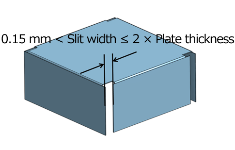
3D model consisting of a single solid (slit width greater than 0.15 mm)
- For shapes that can be formed from a single sheet metal part and have gaps greater than 0.15 mm, selecting “2 × Plate thickness or less” under “Weld location recognition threshold” automatically reduces slit widths of up to twice the Plate thickness to 0.15 mm or less and recognises them as weld locations.
- If the threshold “0.15 mm or less” is selected, these slits cannot be recognised as weld locations.
■Distance recognised as a weld location (With automatic model correction)
Examples of automatic model correction when “2 × Plate thickness or less” is selected as the threshold
Maximum weldable gap: 0.15 mm. The plate is extended as needed to reduce the gap to this value.
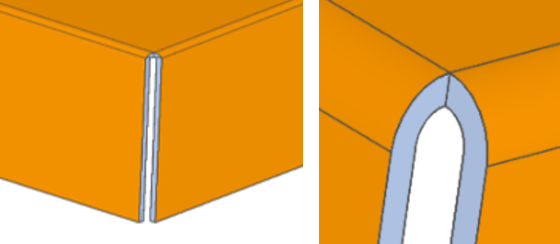
- For models with a Plate thickness greater than 3.2 mm, both plates remain set back at the joint. For models with a Plate thickness of 3.2 mm or less, the joint is converted so that only one plate is set back. (Fig. a)
- For obtuse angles, both plates remain set back at the joint, regardless of Plate thickness. (Fig. b)
Models with a slit width greater than 0.15 mm and no greater than twice the Plate thickness: Before automatic correction
(Fig. b) Obtuse-angled model: The plates are extended to reduce the gap to 0.15 mm while keeping both plates set back at the joint.
Areas identified as weld locations (3D models composed of multiple solids)
3D models composed of multiple solids
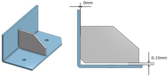
Areas where the distance between solids is 0.15 mm or less are recognized as welded areas.
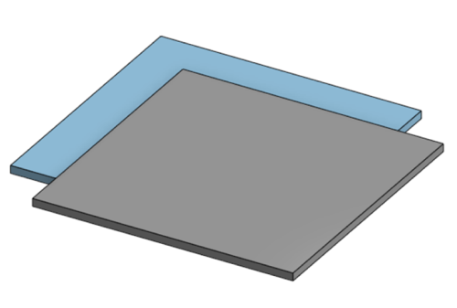
Overlapping plate flat surfaces
Overlapping plate flat surfaces are recognized as weld or spot weld locations along the outer perimeter of the overlap.
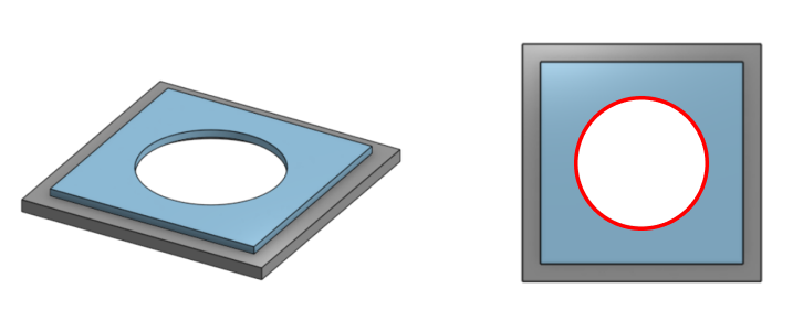
Holes present in overlapping flat plate surfaces
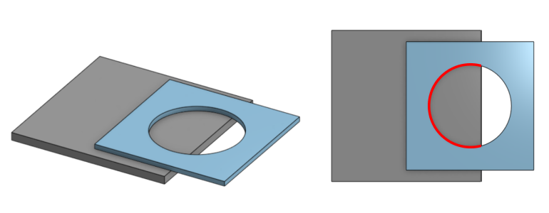
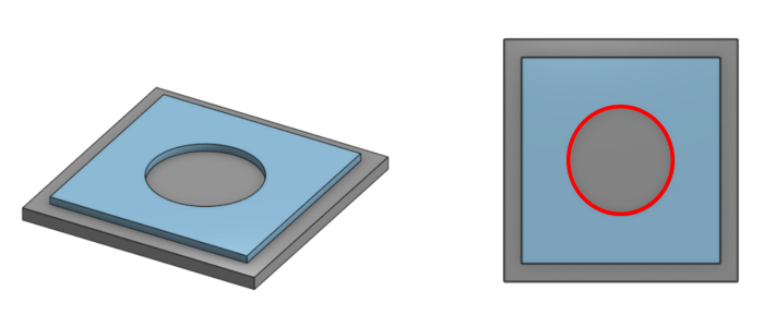
As shown in the figure, in 3D models where one or more parts have holes in the overlapping area, the inner circumference of the hole (red-framed area) is recognized as a welded joint.
| Hole type | Size determined as a welded joint |
|---|---|
| Round hole |
|
| Long Hole | Long hole tip
|
| Angle holes |
|
| Models with holes in square members |
![]() |
![]() |
| Models with holes in both members |
![]() |
Areas not identified as welded sections
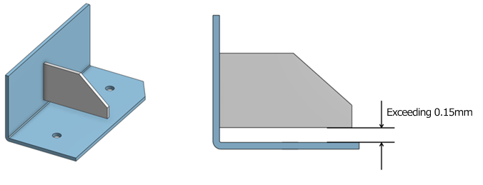
For 3D models composed of multiple solids, areas where the distance between solids exceeds 0.15mm
Areas where the distance between solids exceeds 0.15mm cannot be recognized as weld points.
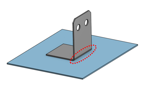
Bent edges on welded sections formed by overlapping plate planes
- As shown in the right diagram, in a 3D model where the flat surfaces of an L- shaped part are overlapped, the edge of the L-shaped bend cannot be recognized as a weld location.
- Edges without bends are recognized as weld points.
Diagonally arranged plate parts
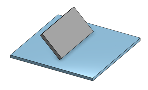
Two solids positioned diagonally cannot be recognized as welded areas.
Curved surface contact points
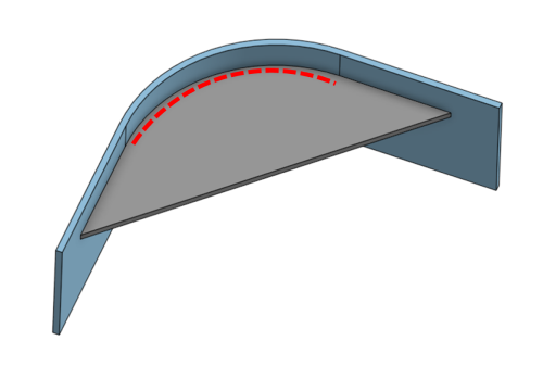
Curved surfaces, such as the inside of a bend, cannot be recognized as weld points regardless of the distance between solids.