Meviy Welded Sheet Metal Service determines the machinability of welded areas and component parts within products.
Refer to the table below for machinability limits or dimensional ranges of welded areas within products.
For machining limits of component parts, refer to the sheet metal part design guideline “Range of Machining Limits“.
However, since the machining limits for components in the Welded Sheet Metal Service differ from those for some sheet metal parts, they are listed in the table below.
*Values may differ from those listed depending on surface treatment, shape, and processing conditions.
*When two or more plate thicknesses are present, the threshold for the thickest plate thickness is applied to the entire product to determine machinability.
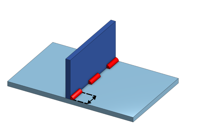
Minimum Weld Length
Processing Limit/Dimension Range
Plate Thickness
Limit Value
EN 1.0330 equiv. (Cold/Hot coiled)
EN 1.0038 equiv.
EN 1.0330 equiv.(electrolytic zinc plating)
Standard (arc or laser)
Arc Welding
1.0
1.0
1.2
1.6
2.0
2.0
2.3
3.2
3.0
4.5
5.0
6.0
9.0
10.0
10.0
12.0
16.0
Sheet Thickness
Limit Value
EN 1.4301 equiv. (No.1)
EN 1.4301 equiv. (2B)
EN 1.4016 equiv. (2B)
Standard (arc or laser)
Arc Welding
1.0
3.0
1.0
1.2
1.5
2.0
2.0
2.5
3.0
3.0
4.0
10.0
5.0
6.0
9.0
10.0
10.0
12.0
Sheet Thickness
Limit Value
EN 1.4301 equiv. (#400)
Standard (arc or laser)
Arc Welding
1.0
1.0
1.2
1.5
2.0
2.0
3.0
3.0
Sheet Thickness
Limit Value
EN AW−5052 equiv.
Standard (arc or laser)
Arc Welding
1.0
5.0
1.2
1.5
1.6
2.0
10.0
2.5
3.0
4.0
15.0
5.0
20.0
6.0
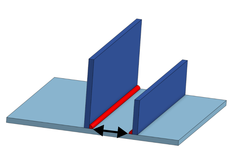
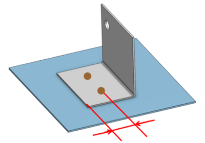
Part Examples
Minimum distance between flat welds
Processing limits/dimension range
Plate Thickness
Guaranteed Value
EN 1.0330 equiv. (Cold/Hot coiled)
EN 1.0038 equiv.
EN 1.0330 equiv.(electrolytic zinc plating)
Standard (arc or laser)
Arc Welding
1.0
4.0
1.2
4.5
1.6
2.0
5.0
2.3
3.2
4.5
6.0
6.0
7.0
9.0
10.0
10.0
12.0
16.0
Plate Thickness
Guaranteed Value
EN 1.4301 equiv. (No.1)
EN 1.4301 equiv. (2B)
EN 1.4016 equiv. (2B)
Standard (arc or laser)
Arc Welding
1.0
3.0
4.0
1.2
4.5
1.5
2.0
5.0
2.5
3.0
4.0
6.0
5.0
7.0
6.0
8.0
9.0
10.0
10.0
10.0
12.0
Plate Thickness
Guaranteed Value
EN 1.4301 equiv. (#400)
Standard (arc or laser)
Arc Welding
1.0
4.0
1.2
4.5
1.5
2.0
5.0
3.0
Plate Thickness
Guaranteed Value
EN AW−5052 equiv.
Standard (arc or laser)
Arc Welding
1.0
20.0
1.2
1.5
1.6
2.0
2.5
25.0
3.0
30.0
4.0
5.0
6.0
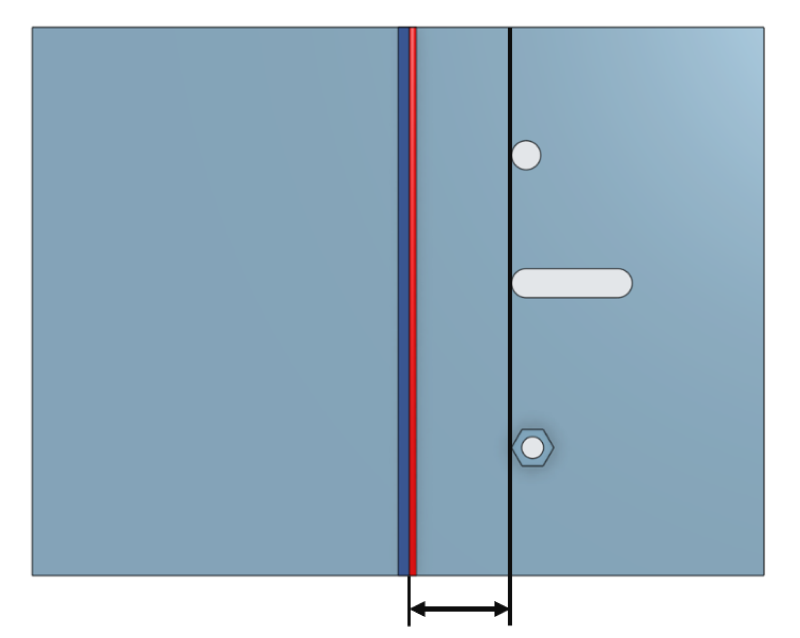
Example locations
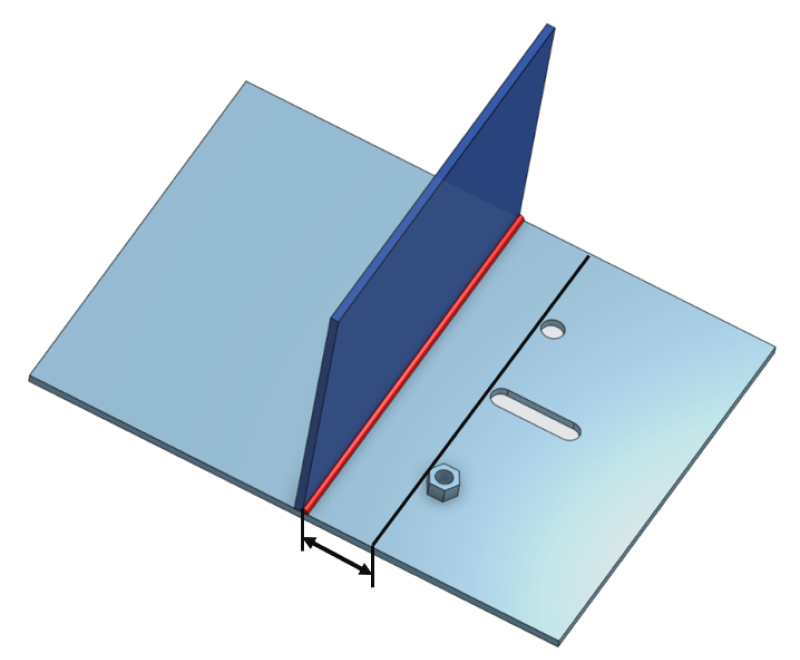
Minimum Distance Between Welded Areas and Various Holes
Processing limits/dimension range
Plate Thickness
Limit Value
EN 1.0330 equiv. (Cold/Hot coiled)
EN 1.0038 equiv.
EN 1.0330 equiv.(electrolytic zinc plating)
Standard (arc or laser)
Arc Welding
1.0
5.0
1.2
1.6
2.0
6.0
2.3
3.2
4.5
8.0
6.0
10.0
9.0
10.0
12.0
16.0
12.0
*Due to manufacturing constraints, for certain iron-based painted products (T Cream (approximate Munsell 10GY9/1) and trivalent chromate (black)), press-fit nuts will be quoted by Manual Quote.
Plate Thickness
Limit Value
EN 1.4301 equiv. (No.1)
EN 1.4301 equiv. (2B)
EN 1.4016 equiv. (2B)
Standard (arc or laser)
Arc Welding
1.0
3.0
5.0
1.2
1.5
2.0
6.0
2.5
3.0
4.0
4.0
8.0
5.0
5.0
10.0
6.0
6.0
12.0
9.0
10.0
10.0
10.0
12.0
Plate Thickness
Limit value
EN 1.4301 equiv. (#400)
Standard (arc or laser)
Arc Welding
1.0
5.0
1.2
1.5
2.0
6.0
3.0
Plate Thickness
Limit value
EN AW−5052 equiv.
Standard (arc or laser)
Arc Welding
1.0
10.0
15.0
1.2
1.5
1.6
2.0
20.0
2.5
3.0
25.0
4.0
30.0
5.0
6.0
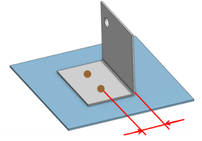
Example locations
Minimum distance between spot weld and hole/plate edge
Plate Thickness
Limit value
EN 1.0330 equiv. (Cold/Hot coiled)
1.0
5.0
1.2
5.0
1.6
5.0
2.0
7.5
2.3
10.0
3.2
10.0
Plate Thickness
Limit value
EN 1.0330 equiv.(electrolytic zinc plating)
1.0
10.0
1.2
10.0
1.6
10.0
2.0
10.6
2.3
11.5
3.2
13.2
Plate Thickness
Limit value
EN 1.4301 equiv. (2B) , EN 1.4016 equiv. (2B)
1.0
6.0
1.2
6.0
1.5
7.0
2.0
9.0
2.5
10.0
3.0
11.0
Plate Thickness
Limit value
EN AW−5052 equiv.
1.0
8.0
1.2
9.0
1.5
10.0
1.6
10.0
2.0
11.0
2.5
12.0
Minimum distance from spot weld to bend
Plate Thickness
Limit value
EN 1.0330 equiv. (Cold/Hot coiled)
1.0
10.0
1.2
10.4
1.6
11.2
2.0
12.0
2.3
14.6
3.2
16.4
Plate Thickness
Limit value
EN 1.0330 equiv.(electrolytic zinc plating)
1.0
11.0
1.2
11.2
1.6
11.6
2.0
12.0
2.3
14.6
3.2
16.4
Plate Thickness
Limit value
EN 1.4301 equiv. (2B) , EN 1.4016 equiv. (2B)
1.0
8.0
1.2
8.4
1.5
10.0
2.0
13.0
2.5
15.0
3.0
16.0
Plate Thickness
Limit value
EN AW−5052 equiv.
1.0
12.0
1.2
12.4
1.5
13.0
1.6
13.2
2.0
15.0
2.5
15.0
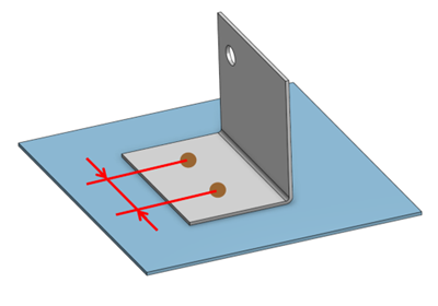
Minimum distance between spot welds
Plate Thickness
Limit value
EN 1.0330 equiv. (Cold/Hot coiled) EN 1.0330 equiv.(electrolytic zinc plating)
1.0
15.0
1.2
17.0
1.6
19.0
2.0
21.0
2.3
23.0
3.2
27.0
Plate Thickness
Limit value
EN 1.4301 equiv. (2B) EN 1.4016 equiv. (2B)
1.0
15.0
1.2
17.0
1.5
19.0
2.0
21.0
2.5
25.0
3.0
27.0
Plate Thickness
Limit value
EN AW−5052 equiv.
1.0
20.0
1.2
22.0
1.5
25.0
1.6
25.0
2.0
28.0
2.5
32.0
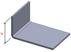
Minimum bend height: Standard bending process
Processing limits/dimension range
Material
Plate Thickness
Limit value h
EN 1.0038 equiv.
9.0
40.0
Part Examples
Bending width dimension specification range
Processing limits/dimension range
Material
Plate Thickness
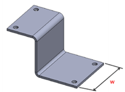
Dimension Range w
EN 1.0038 equiv.
9.0
10 to 500
EN 1.4301 equiv. (2B)*1
5.0
10~850
Part Examples
Minimum angle for sharp bends
Processing Limits and Dimensional Range
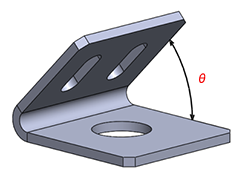
T h e angle θ f o r sharp bends must be 45° or greater.
However, for Welded Sheet Metal services, the θrequirement differs only for the following materials and plate thicknesses.
Material
Surface Treatment
Plate Thickness
Sharp bend angle
EN AW−5052 equiv.
None
1.0 1.2 1.5 1.6 2.0 2.5 3.0 4.0 5.0 6.0
θ ≥ 90
Anodized (White)
Anodized (Black)
Anodized (Matte Black)
EN 1.0330 equiv.*1
None
1.6 2.0 2.3
Electroless Nickel Plating
Trivalent Chromate(Clear)
EN 1.4301 equiv. (2B)*1
–
1.5 2.0 2.5 3.0 4.0 5.0
EN 1.4016 equiv. (2B)*1
–
1.5 2.0 3.0
Part Examples
*1 Due to factory processing constraints, restrictions apply only to long lead time services. If you cannot select a long lead time quote despite being within the applicable range, please contact meviy support.